Giovanni Canestrini’s models of Leonardo da Vinci’s friction experiments
Article DOI: https://dx.doi.org/10.15180/160602
Abstract
Among the exhibits at the 2016 Leonardo da Vinci exhibition at the Science Museum, London, was one that purported to illustrate Leonardo’s experiments on friction. The models involved were the work of Giovanni Canestrini (1893–1975) who contributed to the 1939 and 1953 Leonardo exhibitions in Milan. This article discusses the original sources and history of these models, in the light of recent research into Leonardo’s work on friction. It concludes that, while being relevant to Leonardo’s study of mechanics, these models seriously misrepresent his experimental investigations of friction.
Keywords
friction experiments, Giovanni Canestrini, Leonardo da Vinci, Models, sketches
Introduction
https://dx.doi.org/10.15180/The recent exhibition at the Science Museum, Leonardo da Vinci: The Mechanics of Genius (10 February–4 September 2016) included among 39 models based on Leonardo’s drawings one that was described as a ‘worktable for friction experiments’. It is the purpose of this article to examine the history of this exhibit, to scrutinise the original drawings on which it is based, and to ask what information it really conveys about Leonardo’s studies of friction.
There are two generally accepted ‘laws of friction’, which are broad guidelines rather than fundamental physical laws (Hutchings, 1992). These state that:
- the force of friction acting between two sliding surfaces is proportional to the force pressing the surfaces together (i.e. the two forces have a constant ratio, often called the coefficient of friction), and;
- the force of friction is independent of the apparent area of contact between the two surfaces.
These statements are usually attributed to Guillaume Amontons (1663–1705) and were published by him in 1699. They are often referred to as ‘Amontons’ Laws’, but it is widely known that they were first enunciated by Leonardo da Vinci some 200 years earlier. In a recent chronological study of Leonardo’s notes and sketches relating to friction (Hutchings, 2016) I have shown that his first statement of these laws dates from 1493–1494, and that sketches that are often reproduced and described as showing his ‘friction experiments’ were in fact drawn considerably later. Furthermore, as discussed below, these sketches show experiments that could not realistically have been used to deduce the laws of friction. It was on these sketches that the present ‘worktable’ model, created by Giovanni Canestrini, was based.
Canestrini’s models and his sources
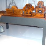
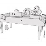
https://dx.doi.org/10.15180/160602/002The exhibit from the 2016 Leonardo exhibition in London is shown in Figure 1, together with a schematic diagram. The accompanying display board stated ‘Leonardo systematically studied friction, which he considered would be important for the functioning of machines. This bench allowed him to experiment with the contact between different surfaces, by distinguishing between sliding and rolling.’ The same exhibit had also been included in related exhibitions in Paris (Cité des Sciences et de l’Industrie, 23 October 2012–18 August 2013), Munich (Deutsches Museum, 11 October 2013–3 August 2014) and São Paulo (Federação das Indústrias do Estado de São Paulo, 11 November 2014–10 May 2015). It belongs, as did many of the other models on display in this loan exhibition, to the Museo Nazionale della Scienza e della Tecnologia ‘Leonardo da Vinci’ (MUST) in Milan where it has inventory number 392.
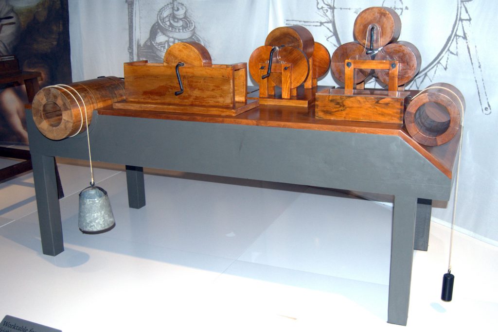
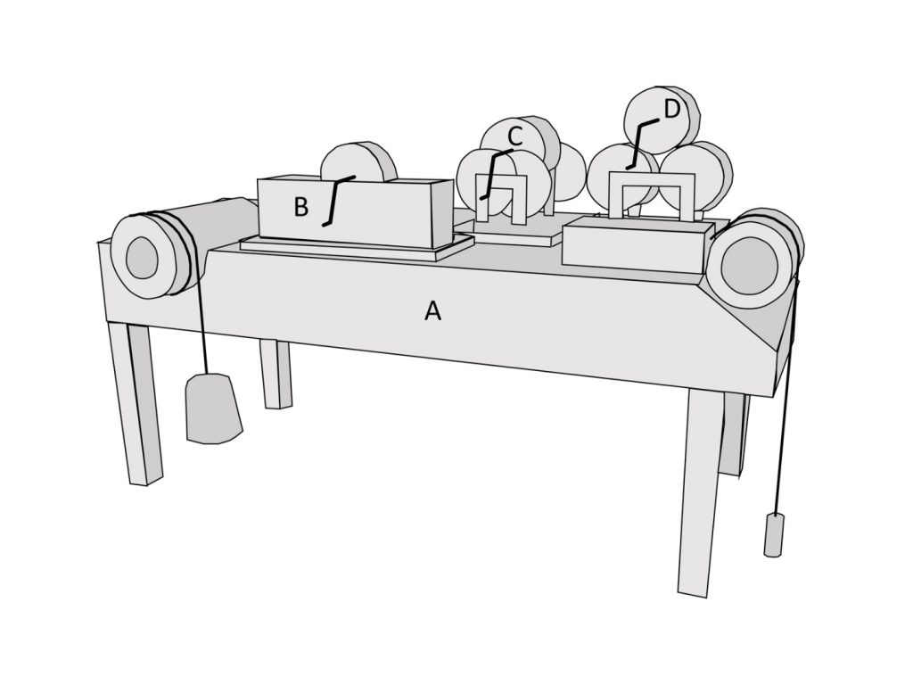
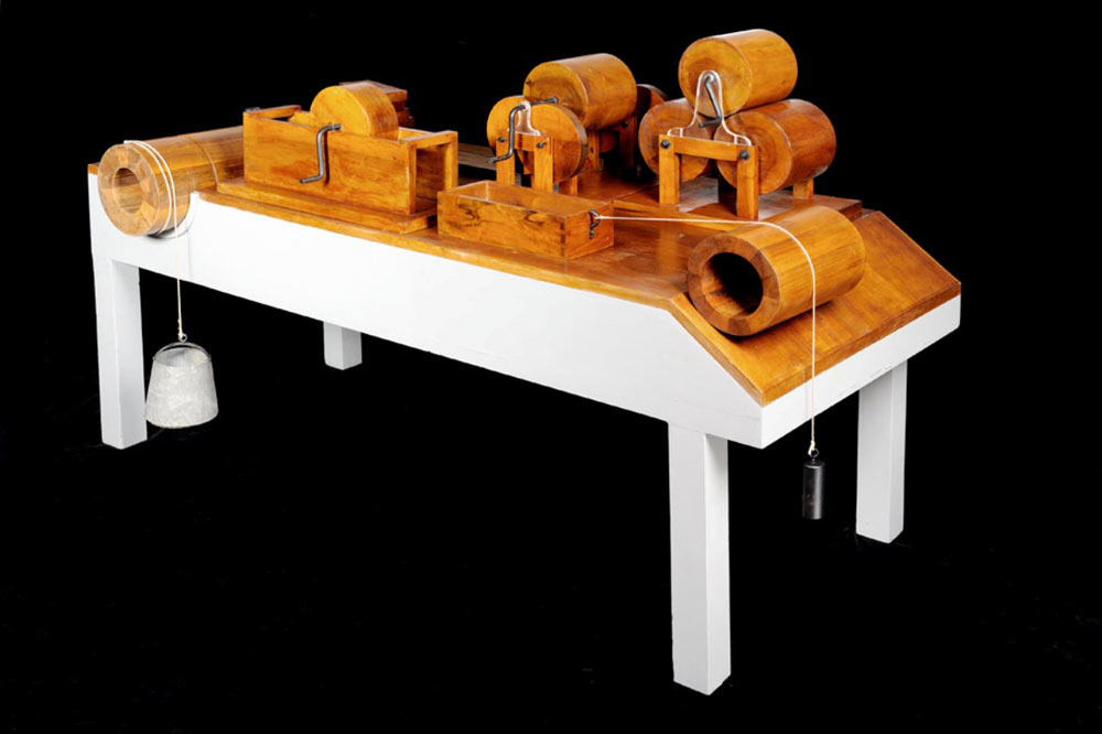

The exhibit consisted of four separate models, although these components all have the same MUST inventory number. The largest was the ‘worktable’, 1.88 m long, 0.81 m high and 0.85 m wide, which we shall call Model A. It supported at one end a rectangular wooden box attached to a string which passed over a cylinder (195 mm in diameter and 320 mm long) on an inclined plane to a hanging weight, and at the other end a horizontal cylinder (237 mm in diameter and 450 mm long) lying in a hemi-cylindrical cavity, again attached to a weight by a string. On the rear left corner of the table lay a wooden plank supporting a stack of shorter wooden blocks, of which one was attached to a long T-shaped handle. The view of these blocks is obscured in Figure 1(a) and they are not depicted in Figure 1(b). On the table also rested three separate devices: Models B, C and D. The models are all labelled in Figure 1(b).
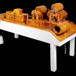
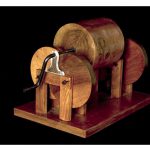
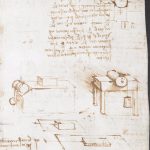
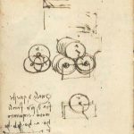
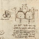
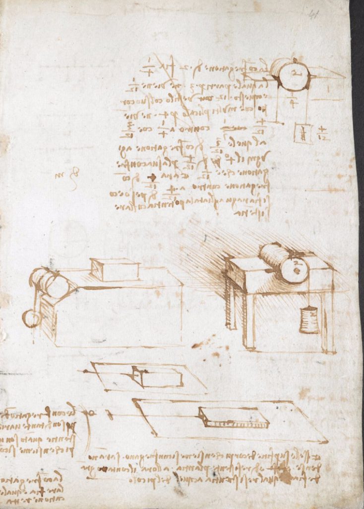
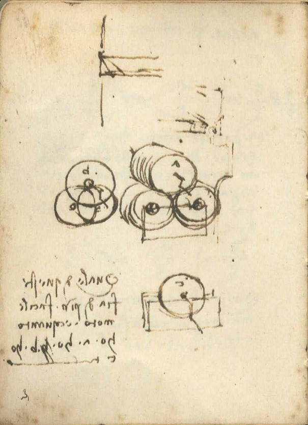
These four models were created by Canestrini for the major exhibition in Milan in 1953, ‘Scienza e tecnica di Leonardo’, and were subsequently donated to MUST where they form part of the permanent collection (Giorgione, 2015). Separate images of the four models are shown in Figure 2. All are based, with varying degrees of fidelity, on drawings contained in Leonardo’s notebooks. Model A is based on sketches from folio 41r of Codex Arundel, which is reproduced in Figure 3. Models B, C and D are based on diagrams found on folio 11v of MS L of the Bibliothèque de l’Institut de France (commonly referred to as ‘Paris’ manuscript L), shown in Figure 4.
Giovanni Canestrini (1893–1975) had a long career as a motor racing journalist, and is famous as one of the founders of the Mille Miglia road race in 1926. He also wrote three substantial pieces on the contributions of Leonardo da Vinci to mechanics, particularly in the context of the development of the motor car. His first essay (Canestrini, 1938) was contained in a volume on the Italian contribution to the evolution and development of the motor vehicle, published by the Reale Automobile Club d’Italia (RACI). It was a detailed account which showed familiarity with much of Leonardo’s writing as well as evidence of wide reading of other sources, and despite the apparent narrowness of the chapter title (‘Leonardo da Vinci and the problems of locomotion’) attempted to show that Leonardo’s contributions had pre-dated and indeed informed the work of later inventors in many fields ranging from geometry and optics, to statics and dynamics, fluid mechanics and hydraulics, military engineering, mechanical devices, metalworking and other areas. In discussing Leonardo’s studies on friction, Canestrini reproduced MS L f. 11v and identified it as showing ‘studies of rolling friction’[1], but while he quoted a statement about friction from Codex Arundel f. 41r[2], he did not reproduce any sketches from that folio.
In the following year Canestrini published two fuller accounts of Leonardo’s work on friction. One (Canestrini, 1939a) was contained within a contribution entitled ‘Leonardo’s machines’ in a collection of essays published in conjunction with the major exhibition of Leonardo’s work and Italian invention held in Milan in 1939. The other (Canestrini, 1939b) was a book entitled ‘Leonardo constructor of machines and vehicles’ in which one of the three chapters was on ‘Friction and traction’. In both works Canestrini reproduced the whole of folio 41r of Codex Arundel. He wrote in the first ‘Leonardo is the first who braved the systematic study of the causes of friction, both for the case of flat surfaces and for the case of axles, preceding by two centuries Amontons (1699) and Coulomb (1781), who reproduced, for his own experiments, the bench which we find drawn on folio 41r of Codex Arundel’[3]. In the second the image of the folio was captioned ‘bench for experiments on friction’[4]. He also reproduced MS L f. 11v, describing it in the two publications as ‘axles rotating on rollers’[5] and ‘studies on the friction in axles’[6].
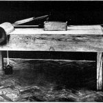
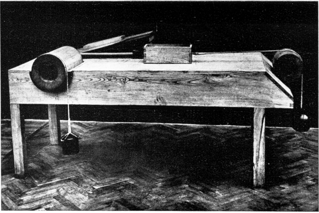
As discussed by Giorgione (2015), the first mechanical models to be based on Leonardo’s drawings were constructed for exhibitions in Florence in 1929, and in Chicago in 1933. These few early models related to aeronautics and textile spinning. Subsequently around 200 models were created and exhibited in 1939, in the context of a major celebration of Italian invention in Milan which included an exhibition devoted to Leonardo da Vinci and was intended by the Fascist government to demonstrate Italian achievements and supremacy in technology[7]. Giovanni Canestrini was one of the engineers involved in designing these models, many of which were built by the RACI, which was heavily involved in organising the exhibition (Giorgione, 2015). Both the official guide to the 1939 exhibition (Guida, 1939) and the catalogue which was published after the exhibition (Catalogo, 1939) list two different models relating to friction displayed within the section on the ‘mechanical arts’: ‘Reconstructed model of bench for experiments on sliding and rolling friction’[8], and ‘Reconstructed model of experimental apparatus for the study of the action of forces and friction in a rotary system’[9]. The first of these was the precursor to Model A that Canestrini created for that exhibition (which we shall call Model A*). There are photographs of Model A* both in his book (Canestrini, 1939b), captioned ‘reconstruction of bench for experiments on friction according to Leonardo’s drawings’,[10] and also in the exhibition catalogue (Catalogo, 1939) with the caption ‘bench for experiments on sliding and rolling friction. Model reconstructed from Codex Arundel f. 41r’[11]. Figure 5 shows one of these images. In all essential elements it was identical to Model A, although in Figure 5 the blocks and plank are arranged to show a block being pulled by its handle (just visible) down an inclined plane.
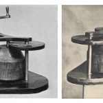
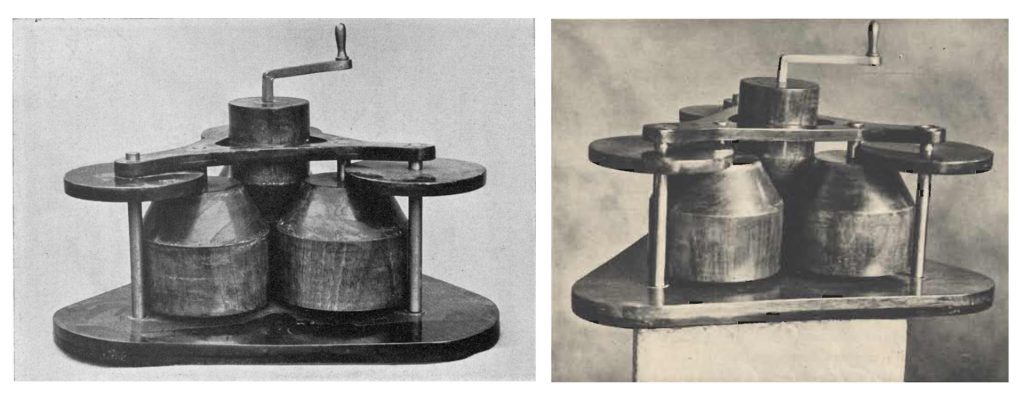
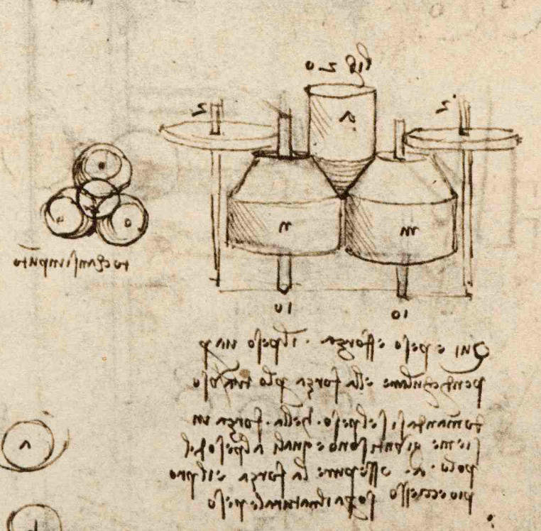
The second model was not illustrated in the exhibition guide or catalogue, but an image is to be found in Canestrini (1939b, p 160), shown here as Figure 6(a), with a caption that closely parallels the entries in both the exhibition guide and the catalogue: ‘Reconstructed model – from drawing by Leonardo – for the study of the action of forces and friction in a rotary system’[12]. This model, which we shall call Model E, is also shown in a leaflet advertising the exhibition (Leaflet, 1939) and depicted in Figure 6(b). The accompanying caption reads misleadingly ‘Cylinder clutch’ or more literally, ‘Clutch made from cylindrical elements’[13]. Model E was based on the sketch in the Codex Atlanticus (f. 1081v) shown in Figure 7, which Canestrini also reproduced in two of his publications. In Canestrini (1938) he described this diagram as ‘thrust rollers in a drawing by Leonardo’[14], while in Canestrini (1939a) it was a ‘system of rotating bearings with thrust rollers on spindles’[15].
There is no record in the catalogue or guide to the 1939 exhibition of any models similar to Models B, C or D, and we must therefore assume that these were created for the first time for the 1953 Milan event.
Discussion
https://dx.doi.org/10.15180/160602/003It is clear from its origins, as discussed above, that the exhibit shown in Figure 1 should be treated as two distinct artefacts: Model A derived from one source, and Models B, C and D which were collectively based on another.
Model A
The ‘table’ of Model A is based on the two central sketches from Codex Arundel f. 41r (see Figure 3) and was first created (as Model A*) in 1939. These sketches date from 1500–1505[16] and show two separate and distinct pieces of apparatus. The notes written on the same page of the notebook, some of which extend on to the facing page (f. 40v), consist of a general statement on the origins of variation of friction, detailed quantitative attempts to evaluate the effects of friction on rotors carrying various hanging weights, and the statement ‘circular friction is equal to linear friction’[17]. But there is no text that relates explicitly or implicitly to the sketches on which Model A is based, and we must therefore interpret them in the context of what we now know about Leonardo’s investigations of friction (Hutchings, 2016).
Leonardo’s first definitive statement on sliding friction (in Codex Forster III f. 72r, 1493–4) pre-dates the diagrams of Figure 3 by some 7–12 years, and by the time he made the sketches on which Model A was based his understanding of friction was well developed. His earliest sketch of a friction ‘experiment’ in the Forster notebook, whether intended to represent a real arrangement or a thought experiment, appears to show a string passing over a pulley. So also do several other later diagrams, rather than the roller that is very clearly drawn in the left-hand central sketch of Figure 3 and embodied in Model A. There is no similar sketch of a string attached to a block and passing over a roller elsewhere in the notebooks, and one can only speculate as to Leonardo’s purpose in drawing the roller in this case. By changing the position of the roller on the slope, the height of the string above the horizontal plane could easily be adjusted to allow blocks with different heights to be accommodated, and this may well have been his intention; the two simpler sketches lower down the page, of blocks on planes with horizontal strings, do indeed show progressively thinner blocks, and are consistent with this interpretation. Alternatively, or possibly additionally, Leonardo may have wished to avoid the effect of friction from a pulley that would otherwise add to the tension in the string that he was trying to measure. The use of a roller on a horizontal plane would certainly have that advantage, but a roller on a sloping plane as shown in the sketch would also add a contribution to the string tension from the weight of the roller. It is not clear from the sketch whether the roller was intended to be a solid or a thin-walled cylinder; the diagonal stroke across the top-left corner of the complete circle could be construed as (inaccurately-drawn) completion of the distal end of an open tube, but the absence of any shading on the ‘inside’ of the tube, as used to show depth elsewhere in the drawing, argues away from that reading. Even if it were a tube with negligible weight, its introduction would have added considerable complexity to Leonardo’s analysis of the experimental results, and we know from his earlier sketches and statements (summarised in Hutchings, 2016) that in his previous investigations of friction he had almost certainly used the much simpler arrangement of a pulley.
The right-hand central diagram in Figure 3 shows an evidently solid cylindrical rotor, with its weight marked as ‘2’ units, supported in a half-bearing[18]. The sketch illustrates a conceptual problem related to the analysis of friction on the surface of a rotating axle that Leonardo tackled in his notebooks over many years from 1493–1495 onwards. He evidently found it challenging but returned to it repeatedly and doggedly in several variants; indeed, a second example is seen at the top of Figure 3. The problem was to find what weight hanging from the string would just overcome the friction between the cylinder and its support, and the difficulty came from the fact that the hanging weight itself added to the rotor’s own weight and therefore enhanced the frictional force. In other sketches and associated notes in Codex Arundel f. 41r and 40v, as well as in many other places, Leonardo made unsuccessful attempts to solve this and the related problem in which weights hang from both sides of the rotor. The methods he used for its analysis were sometimes convoluted and inconsistent, and although he did eventually devise a method to derive a good approximation to the weight needed to overcome friction for a rotor with a single hanging weight when he assumed the value for the coefficient of friction in advance, he cannot have used this geometry as his primary empirical method for investigating friction. What the right-hand central sketch in Figure 3 shows is a relatively well-developed perspective view of a thought experiment he had been drawing repeatedly, either as a flat two-dimensional diagram or with perspective, for perhaps ten years. It is not a representation of an experiment, real or imaginary, to investigate friction, although it does provide an illustration of Leonardo’s correct appreciation that ‘circular friction’ (i.e. the sliding friction between a rotating and a stationary body) is essentially the same phenomenon as linear sliding friction. The drawing does not involve rolling friction, which Leonardo was well able to distinguish from sliding (Hutchings, 2016).
The blocks and plank lying on the table in Model A, and set up to form an inclined plane in Model A*, were evidently inspired by the two sketches of blocks at the bottom of Figure 3, which as we have seen were quite possibly intended to illustrate the effects of varying the thickness of the block. Canestrini appears to have interpreted the sketched line with a T-shaped termination as a rigid bar with a handle, which would be an implausible device with which to attempt to measure a frictional force. In fact, Leonardo sketched a line with a T-shaped end on several other occasions to indicate the direction of application of a tensile force in the same way that we would nowadays conventionally draw an arrow[19], and to construe it as a rigid handle, rather than as a flexible string or cord, is misleading. And it would be wrong to suggest that Leonardo investigated the laws of friction by experimenting with a block on an inclined plane, since despite his efforts this geometry lay outside his powers of quantitative analysis (Hutchings, 2016, p 64).
In using Leonardo’s drawings as his inspiration for the ‘bench’ or ‘worktable’ of Model A* and the subsequent Model A, Canestrini not only created a chimera that combined two quite different devices, but also made other significant changes. As we have noted above, the roller drawn in the left-hand diagram might possibly be solid or alternatively a thin-walled tube, while in the other sketch the axle is definitely solid; neither is a thick-walled cylinder as used in the models. And there is no evidence in the original sketches, or indeed elsewhere in Leonardo’s writing on friction, to support the use of a hollow box rather than a solid block in any sliding friction experiment.
By describing this model as a ‘bench for friction experiments’, Canestrini was following in the distinguished footsteps of Roberto Marcolongo (1862–1943), mathematician and professor of mechanics who carried out extensive research on Leonardo’s mathematical and mechanical investigations. Marcolongo was a member of the Reale Commissione Vinciana and was involved in the organisation of the 1939 Milan exhibition as a member of the scientific committee (Millán Gasca, 2007; Catalogo, 1939). In a lengthy essay on Leonardo’s work on mechanics published in 1933, Marcolongo had reproduced the Arundel drawings and described them as ‘illustrations…of the bench which had served Leonardo for his experiments’[20] (Marcolongo, 1933, p 107). Subsequent writers have echoed the views of Marcolongo and Canestrini, including Reti (1971, p 106), Dowson (1979) and several more recent authors (see Hutchings, 2016). But as we have seen, these sketches and the resulting model provide a substantially misleading impression of the methods by which Leonardo might have investigated sliding friction, and they do not relate to rolling friction at all.
Models B, C and D
These three models, which were first produced for the 1953 exhibition, are based on a group of sketches in MS L f. 11v (see Figure 4) dating from 1497–1502 that show a roller or disc supported in three different ways, with a hand-crank drawn in each case to indicate the roller of interest. They are accompanied on the page by a rhetorical question comparing the ease of rotation for the three designs: ‘which of these is of easier motion, and how much: a or b or c?’.
Model B is the simplest: the roller is attached to a thin axle that is supported in bearings, and the resistance to rotation originates in sliding friction on the axle surface. Leonardo had first studied the friction of axles and the effect of the axle diameter on the frictional resistance some ten years earlier and by the date of these sketches was able to analyse it quantitatively (Hutchings, 2016).
In Model C the axle of the roller is supported on ‘twin-disk’ bearings that Leonardo had previously used in several designs (e.g. in MS B f. 33v, 1487-90; Madrid I f. 12v, 1493-7), and which he knew provided much less frictional torque than the plain bearing used in Model B.
In Model D the roller of interest is supported by two lower rollers analogous to the one in Model B, and drives them by friction. Leonardo was already fully familiar with the concept of a roller or disk driving others by friction, for example using the principle to reduce the effect of frictional torque on an axle in a stack of 24 disks (Madrid I 103r, 1493–7). The way in which the weight of the top roller leads to loads on the bearings is perhaps something that would have concerned him, although there is no evidence for this from the sketches and notes on this page.
In summary, Leonardo already knew in broad terms the answer to his question, and it is likely that his sketches represented a ‘thought experiment’ in which the advantages of these different designs are being compared rather than any real experimental apparatus. The sketch concerns the relative merits of three designs for bearings, and does not represent a method for investigating the friction that would act on the axle shafts or between the rollers. The crank-handles in the drawings are an artistic device to indicate which component is to be turned, rather than suggesting that the torque on it might be measured in some way.
Canestrini’s own descriptions of the sketches behind Models B, C and D varied in his different publications: ‘studies of rolling friction’; ‘axles rotating on rollers’; and ‘studies of friction in axles’. None of these is accurate, as Leonardo’s own words that accompany the sketches make clear: what he was depicting was a comparison between three methods of supporting a roller, and he was asking which method caused the least resistance to motion. As with Model A, these sketches and the models derived from them do not show plausible methods for studying friction, either in sliding or rolling.
Model E
Although Model E was presumably destroyed during the Second World War together with the other models from the 1939 exhibition (Giorgione, 2015; Landrus, 2013) and was not subsequently reconstructed, it provides a further example of a model presented as a ‘friction experiment’, being described in this way by Canestrini (1939b, p 160) and in the exhibition guide and catalogue (Guida, 1939; Catalogo, 1939). Leonardo’s sketch of 1499–1500 (Codex Atlanticus f. 1081v, see Figure 7) on which this model was based clearly shows two lower conical rollers rather than the three used in the model (although three supporting rollers are shown in the neighbouring plan view and four in another sketch at the bottom on the same page). The diagram shows a design for a bearing to support a vertical rotating shaft with a conical end carrying a vertical downward load, and is similar to several earlier designs (1493–1497) in Codex Madrid I (ff. 102v and 113v) which also have two conical supporting rollers. The design is apparently ingenious and superficially attractive, using the cones to support the end of the shaft, combined with horizontal disk bearings to react against the sideways force exerted on the cones. In his accompanying note Leonardo is speculating on the sideways forces that will result from the ‘wedging’ action of the cones. Although the sketch is of a bearing that is intended to have a friction-reducing function, it certainly does not represent any kind of experimental investigation of friction.
In fact, though, the sketch on which Model E was based incorporates a fundamental flaw that would make it completely unsuitable as a bearing, in that the motions of the conically-ended vertical shaft and the two (or three) supporting cones are kinematically incompatible. For pure rolling to occur, which is essential for the device to act as a low-friction bearing and is evidently what Leonardo intended in this and many other bearing designs, the surface speeds of the rolling elements in contact must be the same. With this particular design it is possible to achieve this only at a single height within the device (i.e. on a single plane perpendicular to the axes of the cones); at any higher or lower level there will be slippage, and therefore sliding friction, between the surfaces of the cones. So if the cones make contact over any significant length, as is evidently intended from the diagram, the device will rotate only with considerable effort and would be completely unsuitable for use as a bearing. This is clearly an example of a ‘thought experiment’ rather than an actual practical design.
As we have seen above, Canestrini’s written descriptions of the drawing associated with Model E are reasonably accurate: ‘thrust rollers’ and ‘system of rotating bearings with thrust roller on spindles’. The drawing does indeed show a thrust bearing, in which the end of a vertical shaft is supported on rotating conical rollers, albeit, as we have seen, one that would not actually work. But the description of Model E in the 1939 exhibition guide and catalogue, and also in his book (Canestrini, 1939b), is quite different and erroneous: ‘model of experimental apparatus for the study of the action of forces and friction in a rotary system’. One must wonder whether this change of description might perhaps have been prompted by the discovery, once the model had been built, that it did not perform as either Leonardo or his twentieth-century interpreter had originally envisaged.
Conclusions
https://dx.doi.org/10.15180/160602/004Leonardo’s contributions to the understanding of friction were remarkable, and undoubtedly based on some kind of experimental investigation; it is hard to see that he could have deduced the independence of friction force from contact area (which is counter-intuitive), or obtained quantitative values for the coefficient of friction in any other way (Hutchings, 2016). Kemp (2006) has commented that Leonardo’s methods of investigation were ‘an untidy mixture of deductive and inductive reasoning, habitual observation, hands-on intervention, “thought experiments”, “drawn experiments”, actual experimental testing and analogy’. It is impossible to be sure whether any of his sketches and notes relating to friction represent real experiments that he actually performed, or were illustrations of concepts or of thought experiments[21]. But the discussion above firmly suggests that the sketches used as the basis for Giovanni Canestrini’s models either, despite being concerned with friction, fell into the latter category (in the case of Model A), or have been completely misrepresented as relating to friction experiments at all (in the case of the four other models).
Since the late 1920s numerous models have been constructed and exhibited, based on Leonardo’s ingenious designs of machines, machine elements and measuring instruments, although no other models relate to the investigation of friction. Notable are those created for the 1939 and 1953 Milan exhibitions, including the models discussed above, whose history has been reviewed by Giorgione (2015). The Science Museum has its own smaller collection, produced for the 1952 celebration in London of the quincentenary of Leonardo’s birth and originally exhibited at the Royal Academy of Arts (Bennett, 2015). Models produced in the USA for exhibition in Los Angeles in 1949 were subsequently acquired by IBM and this collection, later augmented, formed the basis of travelling exhibitions from the 1960s to the 1980s (Landrus, 2013). Many of the ex-IBM models together with more recent additions now form a large collection in the Museo Leonardiano in Vinci, while some others are on permanent loan to the University of Technology Sydney, Australia.
The rediscovery of the Madrid Codices provided further inspiration for mechanical models in the 1970s. Several constructed in the 1980s for the Museum of Fine Arts in Montreal were included, together with a couple from the MUST collection, in an exhibition at the Hayward Gallery, London in 1989 (Kemp and Roberts, 1989). The Museo Galileo (Istituto e Museo di Storia della Scienza) in Florence holds a rich collection dating from the 1980s and 1990s, and many of these were included in the only previous exhibition of Leonardo’s engineering at the Science Museum (The Art of Invention: Leonardo and Renaissance Engineers, 15 October 1999–24 April 2000, see Galluzzi, 1999). There are also several commercial ‘Leonardo da Vinci museums’ worldwide, each with its own collection of models of varied fidelity to the original sources. As discussed by both Bennett (2015) and Giorgione (2015), construction of models based on Leonardo’s drawings involves considerable extrapolation and interpolation from the sometimes sparse detail of the original source material.
Interest in Leonardo da Vinci and in his technical achievements remains remarkably high. In this context it is understandable that one might wish to display models to illustrate Leonardo’s experiments on friction. It is perhaps natural to want to base such models, as Canestrini did, on original drawings that show perspective views and are visually more attractive than the rough two-dimensional sketches found elsewhere in the notebooks. But the acid test must surely be whether the viewer can see an answer, or even see that there might be an answer, to the question ‘How might Leonardo have used this for his friction experiments?’. Unfortunately, Giovanni Canestrini’s models fail that test.
Acknowledgements
I am very grateful to Professor Jim Bennett for his encouragement, helpful discussions and valuable suggestions – including, particularly, the idea that the main value of Leonardo models may lie in the detailed examination of the drawings they enforce, which may yield new insights (Bennett, 2015). Dr Susan Mossman kindly arranged to make measurements of the exhibit while it was at the Science Museum.
Tags
Footnotes
Back to text
Back to text
Back to text
Back to text
Back to text
Back to text
Back to text
Back to text
Back to text
Back to text
Back to text
Back to text
Back to text
Back to text
Back to text
Back to text
Back to text
Back to text
Back to text
Back to text
Back to text


