Revealing observatory networks through object stories: Instrumental networks
Article DOI: https://dx.doi.org/10.15180/232004
Abstract
This paper presents three pieces that use objects, or object types, to reveal the material, personal, institutional and commercial networks that surrounded the introduction and successful use of instruments, systems and techniques. The objects explored are: the Hourly Signal Relay, used within the time signal system of the Royal Observatory, Greenwich, from the mid-nineteenth century; photographic glass plates from the British 1874 transit of Venus expeditions; and an electronic imaging tube, Lallemand’s camera, developed in Paris and used at the Lick Observatory in California in the 1960s. Each story uses examples of failure as a means of highlighting a lack of robustness in or effort required to maintain these networks. Once created, however, such networks could, as the second two stories note, go on to develop and support alternative approaches, helping to create success from apparent failure. Nevertheless, complexity, failure and fragility have also led to the underrepresentation or obscurity of these objects in museum collections, until given focused attention in these studies. The paper forms part of a collection of articles: Revealing observatory networks through object stories. The other papers in the collection are ‘Object itineraries’, and ‘Observatory audiences’ and the genesis of the collection is discussed in the ‘Introduction’.
Keywords
astronomy, astrophotography, chemistry, electrical circuits, failure, maintainers, networks, object stories, observatories, photography, physics, scientific expeditions, scientific instruments, time signal system, timekeeping, transit of Venus, user and builder networks
1. Wired in time: the neglected infrastructure of the Greenwich Time System, by Emily Akkermans
https://dx.doi.org/10.15180/232004/001Introduction
…and I cannot but feel a satisfaction in thinking that the Royal Observatory is thus quietly contributing to the punctuality of business through a large portion of this busy country (Airy, 1854, p 8).
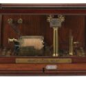
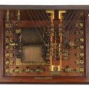
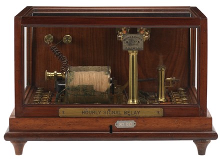
Astronomer Royal George Airy’s well known quote about the Greenwich Time System in 1853 signalled the start of the Observatory’s role in the distribution of time throughout Britain. The system gradually expanded and adapted as its use and reach evolved and developed. The Hourly Relay Signal (Figure 1) is an extremely telling object in thinking about the physical connections of the system, as it only functioned through the wires that connected it to the time signal apparatus at the Royal Observatory, Greenwich. As the timekeeping apparatus at the Observatory became more embedded in the systems of the telegraph and railway networks, so did the apparatus expand and develop to fit within these systems. The Hourly Signal Relay did not operate alone but stood on a desk in what was known as the Computing Room in the mid to late nineteenth century. Wires, relays, batteries and additional instruments were added to the system during the first two decades of its use.
Most of the instruments, and the wires, relays and consumable materials like batteries that made up these physical connections, no longer survive. Because of this, the Greenwich Time System is represented in displays involving only key objects like the Normal Clock, the Airy transit circle, and the Gate Clock. The infrastructure and connections between these instruments are left out of the current display and do not feature much in other accounts of the timekeeping system. A result of this is that an object like the Hourly Relay Signal, which is harder to interpret and, for some, less pleasing to look at, is left neglected in museum storage. However, the timekeeping system was a result of advancements in galvanism and telegraphy, and Airy used these technologies to connect Observatory clocks, telescopes and other recording instruments electrically. The resulting time system automated various observatory procedures, it showed time simultaneously on all the connected dials, and allowed time signals to be sent out externally.
Recent research examining the time system in more detail shows the unreliable nature of this time distribution, the failures that occurred in the system, the challenges of standardising time throughout Britain and the internal and external collaborations that helped automate the system to improve public trust (Gay, 2003; Rooney and Nye, 2009; Ishibashi, 2020). Whilst some of these studies touch upon the batteries, wires and relays that formed part of the system, the focus of this research lies predominantly beyond the observatory walls. Belteki has studied the galvanic connections within the Observatory, the instruments and wires used, with a particular focus on the chronograph and additional instruments important for its function, but this research needs to be extended to other instruments that formed part of the system (Belteki, 2020). The Hourly Signal Relay is just one of these instruments and is one of only two in the collection of Royal Museums Greenwich that once stood on the desk in the Computing Room of the Royal Observatory.[1] It was gifted to the Museum in 1953 and has never been on display.[2] As such, it represents those aspects of the Greenwich time service that are left out of most accounts and, because so much of the system is now gone, it is important to understand and learn from objects like this that do remain.
Greenwich Time System
In 1864, Astronomer Royal George Airy reported to the Board of Visitors that the ‘system of galvanic clocks (containing the Normal Clock, the Chronometer Clock, and the large clock at the Entrance Gate), are all simultaneously adjusted to time by the use, when required, of a galvanic force’. In addition to this,
The Time Signal-Ball at Deal is dropped daily by a galvanic current automatically given by the Normal Clock…. The Post-Office Clocks are regulated mechanically, and signals are sent for regulating the Westminster Clock; and all these, as well as the Deal Ball, automatically report to us the success of the effect of the current which has left the Greenwich clock (Airy, 1865, p 21).
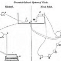
In 1852, Airy had installed a new timekeeping system at the Observatory. It consisted of a regulator and several smaller dials that were connected electrically by copper wires. These were made by the clockmaker and engineer Charles Shepherd and became known as Shepherd’s sympathetic system. With this system, the Observatory used galvanic (electrical) currents to run external sympathetic clocks and supplied time to various railway companies. Airy collaborated with Shepherd and electrical engineer Charles V Walker to set up this system. Initially, it maintained a clock at the London Bridge station of the Southeastern Railway and dropped two time balls: one on the roof of Flamsteed House at the Observatory and one on the offices of the Electric Telegraph Company in the Strand. As the sympathetic system expanded after its installation, so too did the apparatus and wires that were required to operate it (Figure 2).
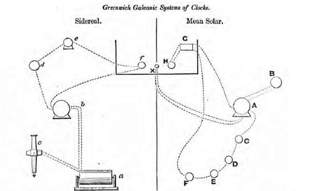
In 1865, William Ellis (assistant to the Astronomer Royal and Superintendent of the Time Department from 1855 to 1874) gave a lecture to members of the British Horological Institute on the Greenwich system of time signals, which was subsequently printed in the journal of the institute (Ellis, 1865). Ellis described the internal function of the system, dividing it into two circuits, one describing the Sidereal connections and the other the Mean Solar connections (Figure 2). The assistants used the sidereal circuit to establish sidereal time accurately and to correct the time of the Normal Clock. In turn, the Mean Solar circuit played a crucial role for time beyond the observatory walls; dropping the time ball for navigators using chronometers and supplying Greenwich Mean Time to telegraph, post office and railway companies.[3]
The Normal Clock at the Royal Observatory in Greenwich is now often described as the ‘heart of Britain’s time system’ and the Gate Clock is well known to visitors.[4] A few of the most iconic instruments are now in the Museum collection. These include the Normal Clock, three sympathetic dials, the Time Ball, and the Gate Clock.[5] All of these can be found in Ellis’s description of the system. Only a few of the instruments from the sidereal part of the circuit are in the Museum’s collection. These are the Airy Transit Circle, the sidereal standard Dent 1906 (added to the system in 1871), and the chronograph.[6] As can be seen in Figure 2, four of the instruments were placed on a desk in the Computing Room. Interestingly, the Hourly Signal Relay was not indicated in this diagram, although it was installed between 1861 and 1862. By 1876, Airy had added three more instruments as the system expanded.
The time signal apparatus in the Computing Room
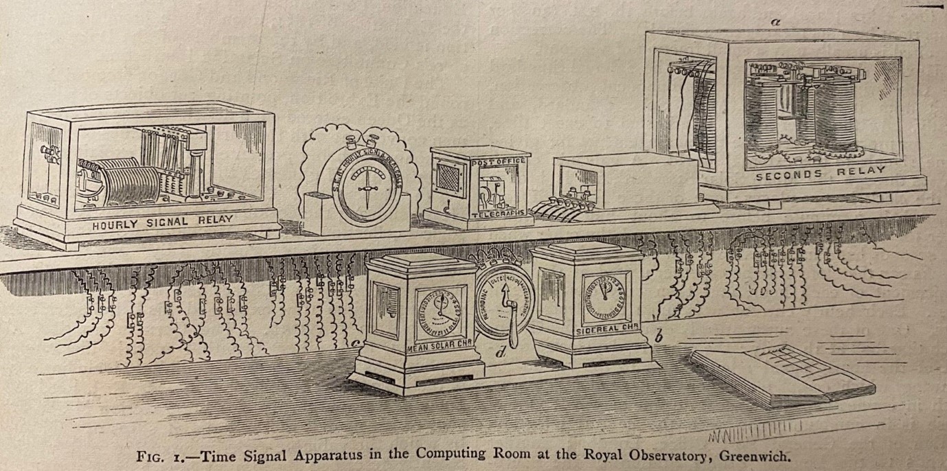
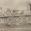
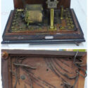
In 1876, Nature published an article on the Greenwich time service with a graphic description of the desk in the Observatory’s Computing Room (Figure 3), with the Hourly Signal Relay visible in the upper-left corner (Ellis, 1876, p 51). Though this image is well known to historians of time distribution, very little attention has been paid to the various objects included in it. It therefore provides a good opportunity to reflect on what is missing from the usual telling of the time signal story. Those objects that have received some attention are the three instruments on the bottom shelf (Ishibashi, 2020; Belteki, 2020). The mean solar chronometer on the left was connected to the Normal Clock, whilst the sidereal chronometer on the right connected to the sidereal transit clock. In between the two sat a commutator. The assistants would establish the error of the sidereal transit clock by observing clock stars with the transit circle.[7] The chronograph recorded the time of the transit, which the assistants compared to the time recorded by the transit clock. With the error of the transit clock known, they could readily calculate the error of the Normal Clock in the Computing Room by comparing the sidereal and solar chronometers. With the error established, the assistants could use the commutator to adjust the time of the Normal Clock. Moving the handle to the right would accelerate and to the left would retard the oscillation of the pendulum. In this way, the assistant could adjust the time of the Normal Clock and all the apparatus connected to it without leaving the Computing Room. Corrections were made daily before 10am and 1pm.
If the objects on the bottom shelf were important for the internal arrangements of the time system, then the instruments on the top shelf extended this time beyond the Observatory walls. Initially, the Normal Clock, the Ball Trigger (the apparatus connected to drop the Time Ball) and the external connections were all in the same circuit. The Hourly Relay Signal, made by the firm Morris and Mapple, was installed to separate these external signals from the currents that operated the internal currents and dropped the time ball, and to expand the number of external signals that could be completed.[8]
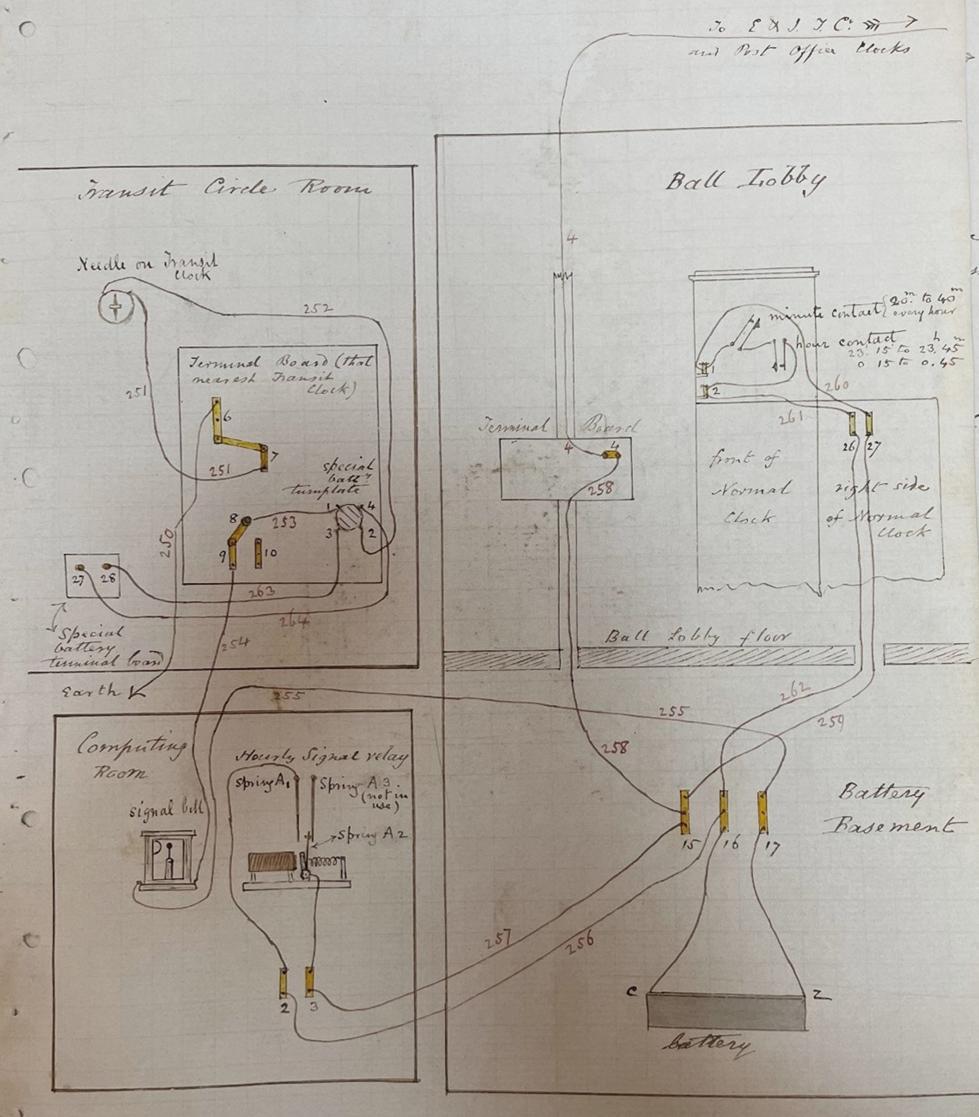
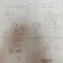
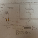
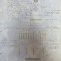
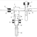
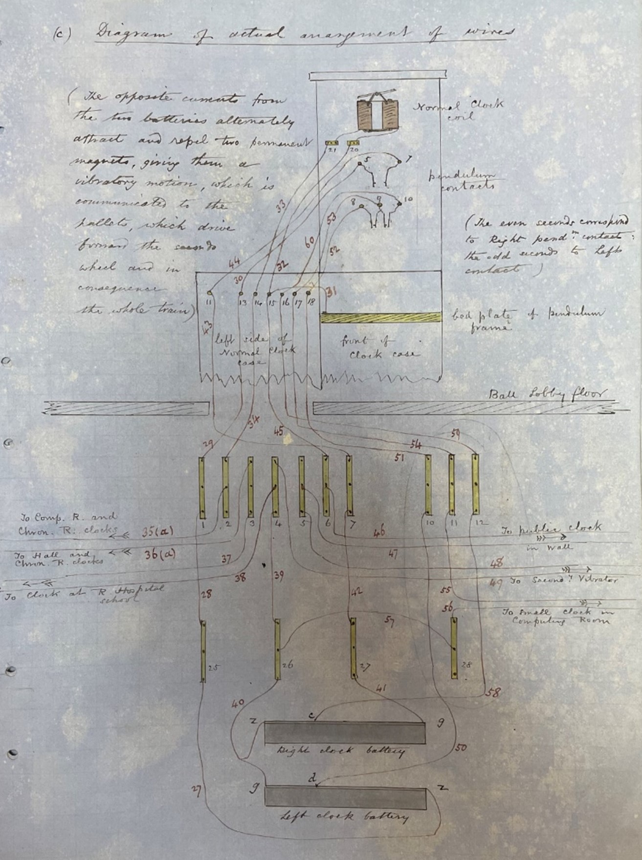
As can be seen in the diagram above (Figure 4), the Hourly Signal Relay was connected to terminals on the right side of the Normal Clock (which was then located in the Ball Lobby) and a battery in the Battery Basement. The yellow rectangles depict connecting bars of copper that conducted the currents. Each wire was numbered.
Each hour, the electro-magnets of the Hourly Signal Relay closed several circuits that sent currents outside the observatory. The best description can be found in a manuscript entitled ‘Description of the Galvanic Connexions, apparatus, and methods of action as existing at or in connexion with the Royal Observatory, Greenwich’, dated April 1862, which was likely written by the assistant William Ellis.[9] Here we find the descriptions of the various wires and circuits that sent out time signals.
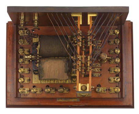
Examining the object itself, we can see that each of the six circuits in the Relay consists of wires and contact points, 18 of which are visible along the left, right and front of the instrument. These were labelled [A1, A2, A3], [B1, B2, B3], [C1, C2, C3] etc. continuing to [F1, F2, F3]. Ellis’s ‘Description’ shows that circuit A sent signals to the Electrical and International Telegraph Company, circuit B sent signals to the South Eastern Railway and dropped the Deal Time Ball, and circuit C sent signals to the London District Telegraph Company. There is no description of circuits D, E and F being connected at this time (April 1862), and Ellis mentions in his lecture that in 1865 only three of these circuits were in use. The Relay could complete up to six external connections, but whether all of these were ever realised requires further research.
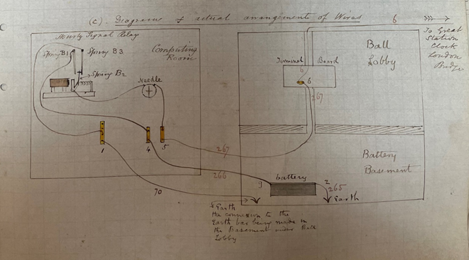
From the description it is also unclear exactly which parts of each individual circuit might be activated at each point. For example, only in the diagram showing the circuit to the South Eastern Railway and the Deal Time Ball is spring B3 noted as a contact point. According to this circuit, the spring B3 leads to a connection with Earth, so this part may only have been activated for the return signal from Deal, as this was monitored for accuracy at the Royal Observatory. In the diagram depicted in Figure 4, A3 is noted as not being in use. It is clear from this description that not all the circuits were in use, and further research might help identify when and where the additional connections were made.
Little is known of the other four objects on the upper shelf of the desk in the Computing Room shown in Figure 3, and it may be that not all of them were present in 1862. Directly to the right of the Hourly Signal Relay is a galvanometer marked ‘S.E.R. Hourly Signal & Deal Balls’. Next to this is a bell signal marked ‘Post Office Telegraphs’ and beside this another object that bears no markings and little other identifying features. Both the S.E.R. Hourly Signal and the Post Office Telegraphs apparatus indicated to the assistants that a current had passed along the wires (Ellis, 1876). On the right-hand side of the shelf sat the Seconds Relay. It was driven directly from the Normal Clock and was connected to the Mean Solar Chronometer on the desk. Ellis did not describe the Seconds Relay in his ‘Description of the Galvanic Connexions’ but he did mention it in his lecture given to the Horological Institute. In 1866, Airy explained that the South Eastern Railway, which had a ‘clock, the property of the Royal Observatory…governed by a current at every second from the Royal Observatory’ (Airy, 1866, p 23). It is highly likely that this, or an additional Seconds Relay, provided these currents.
The evolution of the time desk would be of particular interest, considering the further developments to the system that occurred in the late nineteenth and early twentieth century. In 1893, a regulator made by the firm Dent & Co. replaced the Shepherd Normal Clock as the Mean Solar Standard Clock (Howse, 1975).[10] In the same year that the Hourly Signal Relay transferred to Chatham (1922), Airy’s successor, Frank Dyson, installed a new Cottingham-Riefler regulator, which was far more accurate than the Dent. This was superseded only three years later by the Shortt Free-Pendulum System, increasing the accuracy of the system and creating ‘a development in time-keeping as fundamental as the invention of the pendulum clock 250 years before’ (Howse, 1975, p 142). Further developments led to the use of telephone and radio for time distribution in the 1920s. Exploring whether any of the apparatus of the time system remained in use during this period, and why this object transferred to Chatham, could help reveal what happened to the rest of the objects shown in Figure 3 and would, therefore, be a great opportunity for further research.
Missing connections and troubleshooting
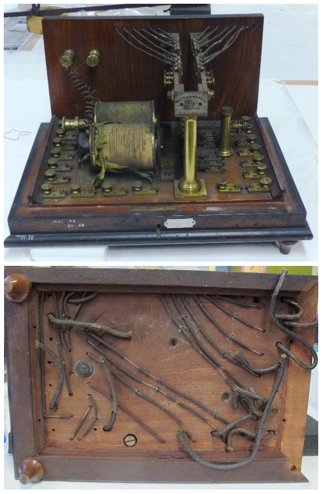
At some point, the wires leading from the Hourly Signal Relay were cut, marking a direct and definitive end to its life as a working object. As its specific function was dependent on the wires connecting it within the time system, it was not repurposed for other use. The cut wires also signify additional materials that formed a crucial part of the internal system but are rarely touched upon in accounts of the Greenwich Time System. This provides a chance to reflect on the other missing elements from the system: the network of wires, relays, contact points and batteries that made up this physical network of time. Remnants of this system and other supporting instruments can now be found in empty holes and electrical fittings present on these objects, from which wires would have spread throughout the observatory. These are also evident in the Normal Clock, now on display in the Time and Greenwich gallery.
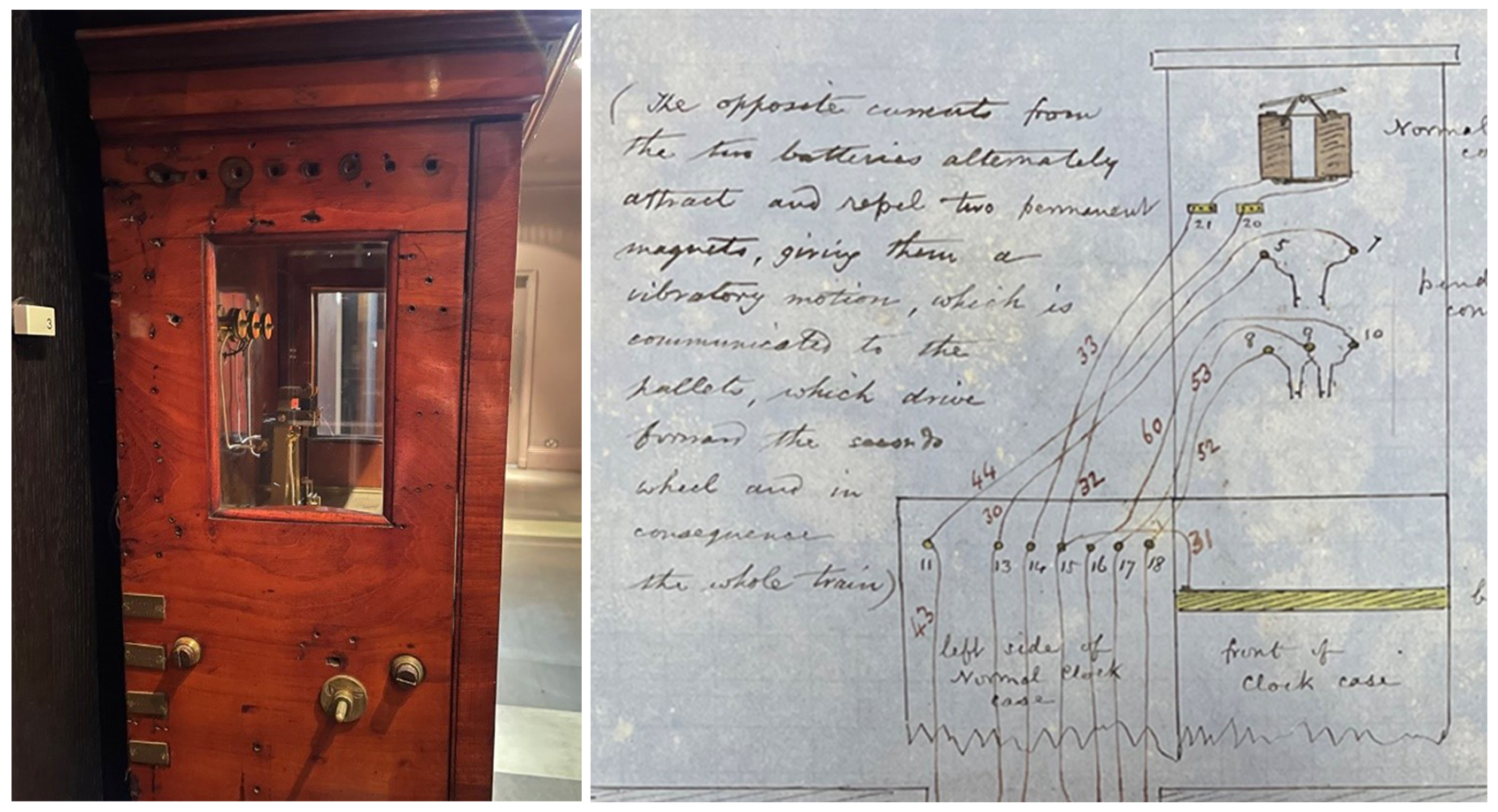
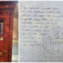
Figure 8 shows the many contact points that once connected the Normal Clock to the rest of the system. The diagram on the right in Figure 9 formed part of Ellis’s ‘Description’. Here, he listed the terminals that connected the various objects and apparatus. Ellis lists amongst others, for example, 52 terminals in the basement, 25 terminals in the Computing Room, 28 terminals in the Transit Circle Room and four terminals in the Ball Lobby. The Normal Clock had 29 terminals, some of which can be seen on the image to the left. This demonstrates the large number of instrument embedded in the network and the complexity of maintaining such an elaborate system.
From the terminals on the clock, the wires ran down to the connecting bars in the Battery Basement. These connected the clock to other instruments within the observatory and directly to a clock at the Royal Hospital School. Each terminal, contact point and wire was numbered. This was essential for the astronomer and the assistants to locate and remedy any failures. As the system expanded, so did the potential points at which the circuit could fail as the following memo shows: ‘the normal clock went wrong (slow) some 16s or 18s during the night. Whether the fault is in the contacts or in long wires I have not made out. It is not I believe in the battery.’[11]
Prior to this system, any error in timekeeping would often be limited to the usual problems that regulators were subject to, which could be remedied by either the astronomer or a clockmaker. The new connected system required networks of additional people and companies for supplies, maintenance and troubleshooting. And another problem arose: if one clock failed, this affected other clocks in the network, as a note from Airy to Ellis illustrates: ‘get your sidereal chronometer in order. My sympathetic clock will not go.’[12] Potential failure of the system could be down to poor battery power, degraded or disconnected wires, faulty contact points, and wrong connections made between circuits. For example, at one point ‘a sine plate having broken in the battery that brings the signal relay into action’ meant the 10am and 1pm signals did not go out.[13] Degradation of the material proved problematic when the wires under the ‘casings on south wall of building’ were found to be in ‘wretched condition, the gutta percha having shrunk in scores of places’. These had to be replaced but there was not enough wire in store, so Ellis ordered ‘one half mile piece of new wire’ from the India Rubber, Gutta Percha & Telegraph Works Company.[14] Even the cleaning of the batteries would interfere with the system: Ellis ordered this to be done at set times, and to cover up the Gate clock during the process.[15] Although the idea was that the system was fully automated, human error could not be eliminated. Junior assistant William Thynne Lynn ‘forgot to raise the trigger levers of the Ball, which threw all the signals into confusion. I have told him that he had better arrange with you to have six or eight days practice to acquire the habit of doing all in order.’[16]
Conclusion
The current narrative of the Greenwich Time System, focusing on the transit circle and the Normal Clock, implies a straightforward adoption of a static system that remained in place for forty years. However, this simplifies a developing system that expanded and adapted to the growing needs of its distributors and users. Following Airy’s initial installation of the system in 1852, it expanded in the 1860s and 1870s.
The Hourly Signal Relay is a highly interesting object through which to think about object histories and their relation to missing elements within the historical physical networks in which they operated. This object speaks to this on two levels: it is only one of two objects that RMG has in its collections in relation to the desk in the Computing Room; and it could not function without the wires, relays, batteries and other instrument to which it was connected. This also reminds us of the need for connections with external people and businesses that could supply materials, skills and knowledge required to keep the system operational.
From this object, the description of the circuits and the image of the time desk, it is clear there is still much to learn about the physical networks within the observatory that formed a crucial part of the late nineteenth-century time service. Technological systems operate in complex networks involving people, instruments, procedures, repairs and replacements, which adapt and evolve to the changing requirements in which they are used. The Hourly Signal Relay as a Museum object, Ellis’s published account of its use, and the archival descriptions of the system help us understand how objects on display, such as the Normal Clock, were embedded in networks such as these. It takes the narrative beyond what has survived and is on display, to inform us about the systems of its use. This short account has emphasised the material aspects of this network in particular, but suggests the fruitfulness of further research on its maintenance and repair, and on the people involved in its upkeep.
2. Photographic networks in the Venus transit, by Kelley Wilder
https://dx.doi.org/10.15180/232004/002Introduction
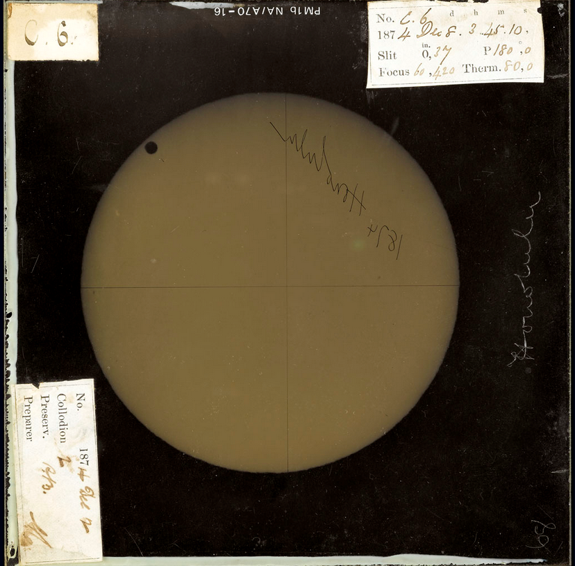
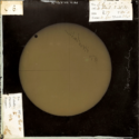
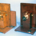
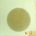
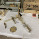
Figure 1 is the kind of object often overlooked. It is a photographic copy positive on glass, just shy of 6 inches square (15.2 x 15.2 cm) and about 1 mm thick, showing the Sun’s disk, with the small figure of Venus at the top left, transiting the Sun in 1874. Despite its richness as a ‘material complex’, demonstrated in this short article, the plate’s characteristics have conspired against its conservation as an important heritage object (Smith, 2014, pp 8–14). It is a copy photograph, not the ‘original’ negative, and by implication not unique. Like its negative, it has no precise authorship. And it was not the origin of a discovery, or indeed any important scientific knowledge. It is an example of one among the roughly one thousand photographic negatives, doubled in copies, made during the British Transit expeditions (Ratcliffe, 2008, pp 64–65).
Although the plate and its many companions occupy an ambivalent space in astronomical history, representing a failure of photography to produce precision astronomical data, they indicate the indelible insertion of photography on glass into astronomical networks. The failure of the photographs to produce knowledge lay in the astronomers’ inability to resolve the plate measurement, taking into account irradiation and irregularly shaped profiles of Venus in exposures from different stations (Ratcliffe, 2008, Ch 6). However, the widespread use of photographic materials (even unsuccessfully) indicated an investment of time and money by astronomers in a new network of recording photographically on glass, one that would grow and expand to underpin many astronomical activities of the twentieth century.
Despite the transit’s place as an important early international use of photographic technology in astronomy, very few of the negatives, or their copy positives, can be found in archives. The positive in Figure 1 accompanies a group of unknown provenance at Royal Museums Greenwich: two further positives, from Rourkee, and Luxor; one negative, very likely from Rodriguez; and three Janssen plates, two negatives and a positive, two of which are mounted in wooden holders. The group’s material and geographic spread suggest that they may have been gathered together for exhibition. While it could be that the small surviving numbers of transit photographs are the result of breakage in the handling of the glass, they are more likely neglected because they are considered failures.[17] However disappointing the images were to astronomers at the time, or astronomical historians since, this collodion positive and its companions (negative and positive) can tell us a great deal about the kinds of photographic and industrial networks that were important not only to astronomy, but to the growth of photography at a time when the nascent photographic industry was turning from a cottage industry, largely conducted by wealthy individuals at home, into the industrial, international industry that emerged fully after the First World War and dominated much of twentieth-century science.
Training for the transit
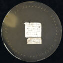
Transits are a sort of industry in themselves, occurring regularly but infrequently, and often accommodating new technology like photography (see Chinnici, ‘Object itineraries’). The investment, as discussed elsewhere in this collection (e.g. Biro, ‘Observatory audiences’), by colonial powers, like Germany, France, the UK, the Netherlands, the USA and others, was considerable. It led to the making of an unprecedented number of photographs, running into the multiple thousands (and likely underestimated), and the training of numerous photographers. The numbers of estimated negatives probably included only the ‘successful’ photographs, and not the total number of plates exposed and ruined, or broken in transit, and certainly it does not take account of the numbers of copies, or the test photographs made during the training of photographers, like this Janssen plate in Figure 2.[18] The documentation that such an international effort produced has clarified for historians the kinds of international supply lines in which early photography was involved.

The journal of Captain George Lyon Tupman, who was a key observer in the British transit expedition, and instrumental in the attempted reduction of the data, gives a sense of the scope of the preparations.[19] As early as November 1873, trainees had gathered at Greenwich to practise their observations and construct, test and calibrate the instruments. Among them were Lieutenants of the Royal Navy Corbet, Ramsden and Hoggen, Father Perry from Stoneyhurst, Mr Smith and Royal Engineers Lieut. Palmer, Leonard Darwin and Captain (later Sir) William de Wiveleslie Abney. Ramsden, along with three sappers (military engineers) as photographic assistants, organised the photographic output from Honolulu, where Tupman was also stationed. It is important to say ‘organised’ and not ‘took’ the photographs, because the making of photographs in the transit was not an individual activity and a single person cannot be ascribed authorship of any of the resulting images. This point is worth emphasising as one of the advantages of turning from studying people to studying objects and their trajectories. Seeing the transit photographs (and indeed astronomical photography in general) as the outcome of the effort of several people in the making, taking and reading of photographic images allows us to begin to understand the expanded network of individuals involved in observatory activities.
It helps to clarify the mechanics of how collodion photography was made on the expeditions, and how the people who made them were trained. The negatives, when they were created in situ, were produced in stages, with one person cleaning the glass, another preparing the plate, then someone else inserting the plate and making the exposure, then yet more people to develop, fix and wash the plates immediately after exposure. Each negative was handled by four or more people. This copy (Figure 1) was likely made in the days following the transit itself, to secure the image in case the originals were broken, before dismantling the camp and sailing home. Individuals trained in Greenwich under first Abney and then Abney’s delegate, Leonard Darwin, were named as photographers on the expeditions. The sappers, who seem to have been trained elsewhere, or even on site, are often not acknowledged. It is not clear who made the copy positives but, given the sheer volume of photography, likely all trained personnel took part in this copying. Although historians rely heavily on Tupman’s accounts to identify photographers, not all the named photographers were trained at Greenwich. John Waterhouse, who photographed in Rourkee, trained alone in Calcutta before joining his station, relying on written texts and experiments to achieve his photographs (Waterhouse, 1875, p 53).
Astro-photographic networks
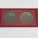
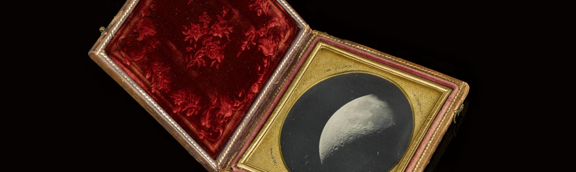
Even before these photographers began industriously training, however, two men at the centre of the photographic community shaped the photography of the transit. The businessman, astronomer and photographer Warren De La Rue set the British photographic endeavour in motion, and the chemist, photographer and author Abney ensured its execution. At almost double Abney’s age, De La Rue did not travel to observe the transit, but his heliograph design and enthusiasm for celestial photography forged important links between astronomical and photographic circles. Inspired by John Adams Whipple and Antoine Claudet’s Moon daguerreotypes exhibited at the Crystal Palace in 1851 (Figure 3), De La Rue entered into photography by mastering the tricky techniques of wet plate collodion, and by the end of the decade, employing his assistant Mr Reynolds, became a prolific and accomplished lunar photographer.[20] He was equally trailblazing in monetising his photographs through publication. Taking advantage of the 1842 British Copyright Act, in 1862 and 1863 De La Rue sold the copyright of six of his photographs of the Moon to instrument maker and publisher Smith, Beck & Beck, who printed them as stereo cards.[21] Smith, Beck & Beck were deeply invested in the stereo craze sweeping photography, selling both cards and stereo viewing devices manufactured at their optical works in Holloway (Figure 4).
The Moon images were just the beginning of an emerging market for science photographs in the 1860s and 70s that would encourage the Royal Astronomical Society (RAS) to begin a Photographic Committee in February of 1891, charged with acquiring ‘valuable’ astronomical images and their copyrights, and arranging for them to be copied, printed and sold through Eyre & Spottiswold, formerly the Woodburytype Company.[22] The committee was successful in procuring and selling famous images of eclipses, comets, nebulae and sunspots, reporting a steady annual income.[23] Transit photographs like Figure 1, however, do not appear in the photographic stock of the RAS, in spite of being the first photographs of the Venus transit, and visually quite striking. The cloud of failure seems to have rendered them deeply undesirable artefacts, even if they were photographic firsts. Or, perhaps the collections were already discarded or disbursed by the time the RAS committee was formed and began seeking saleable content.
After his election to the Kew Committee in 1854, De La Rue began working with Dallmeyer, the optician who was to become a household name in camera equipment (Macdonald, 2018, p 94). Dallmeyer, who was a member of the Photographic Society (later the Royal Photographic Society or RPS), turned his knowledge of telescope lens manufacture to camera lenses in the 1860s, creating a patented portrait lens for photographic studio work, manufacturing cameras, and eventually supplying lenses for cinema cameras. Other manufacturers, like Thornton Pickard, often used Dallmeyer lenses, which became a trade name for precision and quality.
Abney’s photographic plates
Abney, at just 31 years old and new to astronomy, took up the challenge of making De La Rue’s heliograph work in the field, introducing his own albumen-beer dry collodion process, in place of the wet plate.[24] It is important to think about the manufacture of collodion plates to understand the step-change that Abney’s process brought – or should have brought, had it been uniformly used. True wet plate collodion photography, introduced by Frederick Scott Archer in 1851, required individual plate processing. Once the collodion dried, it could no longer be wet again, so all plate preparation, exposure, development and fixing had to take place on the spot. The ‘dry’ plate invited batch manufacture, which, while still variable to a degree that we can hardly imagine today, was nonetheless subject to some more controls than individual plate preparation. The plates kept for some time: Abney prepared 120 plates in London and travelled with them to his station in Egypt (Abney, 1876, Ch 4). His instruction manual even indicates that the plates could be stored up to forty days before developing (Abney, 1874b, p 277).
Controlling the site of manufacture, and with it the variability of the photographic plate ‘speed’ and grain size became the focus of every plate manufacturer for nearly the next century. For scientific purposes, it was considered critical. Ratcliff and others have discussed the debates that occurred in the photographic and astronomical press about the advantages and disadvantages of daguerreotype, wet plate and dry plate photography for the transit (Ratcliff, 2008, pp 59 ff). However, even making a ‘decision’ on paper didn’t guarantee the successful application of Abney’s process.
So-called ‘dry’ collodion plates are not to be confused with the ‘gelatine dry plate’ that emerged in the late 1870s and eventually became the standard for photographic plates. ‘Dry’ collodion of the sort Abney recommended was not entirely dry, but tacky due to the addition of preservatives. Abney’s process used readily accessible preservatives in the form of egg albumen and beer – in this case ‘bitter or mild ale’ (Abney, 1874b, p 275). Procuring the materials to enable uniform and reliable photographic results required some planning. Abney took with him beer from London, as well as dry powdered albumen – no doubt preferable to travelling with live chickens. Ramsden, too, successfully employed the albumen-beer process for the negatives. However, the positive copies like Figure 1 were quite likely made using the more common, and less volatile, wet plate method.
Abney also recommended a particular commercial collodion, from the chemist R W Thomas of 10 Pall Mall. Thomas, later R W Thomas & Co, maintained a photographic supply house that ran until at least the turn of the century.[25] Thomas’s establishment was one of many such suppliers, who built their businesses from the 1850s to the 1870s in supplying materials and expanded into manufacturing with the growth of the glass plate manufacturing industry. However, the albumen-beer process, although successfully deployed by Abney and Ramsden, did not serve at all the Venus transit stations. In India, John Waterhouse had little success with it, which he put down to different brewing methods introducing unknown substances into the beer. He also worried that the variability of beer production might render the plates incomparable to one another. Waterhouse’s experiments using laudanum, morphia (morphine), tea and, his eventual choice, coffee as a preservative indicate not only a complexity of substances, but also the colonial inflections of photographic operations (Waterhouse, 1875, pp 56–58).
Photographic materials were part of international trade even in the 1870s, with paper, chemistry and images flowing freely along international and colonial trade routes (Mintie, 2020). Waterhouse eventually settled on the coffee recipe, but made use of the traditional wet plate recipes as well to supplement the photography at Rourkee. Ratcliff has remarked on the considerable ‘variation in the colours and textures in the photographic emulsion’ of the transit negatives and positives (Ratcliff, 2008, p 120). This was a result not only of different recipes used to make the emulsions, but also occurred with different exposures. Abney recorded that ‘an under-exposed picture has an image of slate colour; an over-exposed picture has one of an olive green; whilst one properly exposed is of a rich chocolate brown’ (Abney, 1874b, p 278). Such variations are evidence of the individual practices at each station, and by each operator, in spite of Abney’s attempt at standardisation across the British expeditions. It was these sorts of variations, in addition to grain size and aberration of the irregular form of Venus against the Sun in some exposures, that frustrated Tupman’s and others’ eventual reduction of data from the photographs.
Abney’s photographic networks
Abney’s invention of a particular recipe for dry collodion was not unique, rather it was part of a pattern in the photographic industry. Recipes abounded by Fothergill, Hill Norris, Russell, Taupenot, and many others. Some, like Dr Richard Hill Norris, physiology professor at Queen’s College Birmingham, having hit on a successful recipe, marketed these into lucrative businesses in manufacturing dry plates. Other inventors, like Abney, advanced their ideas not through manufacturing, but through the publishing of manuals and handbooks.
Even before the transit, Abney had attempted to create standards for photographic production of the Royal Engineers, by publishing his Instructions for Photography for use at S.M.E. Chatham in 1871. In 1874 he republished this work, in a larger print run and simultaneously in the USA and Britain (Abney, 1871 and 1874a). Like his British publications, which were printed by the School of Military Engineering, the American edition was printed by the Army Engineers. Abney’s training of so many engineers in photography, both through the photography school at Chatham and through their involvement in Transit photography, was merely the beginning of an illustrious career in photographic and science education. The trajectory toward education perhaps explains Abney’s exceptional publishing career. Instructions went through ten editions by the turn of the century, and he followed it up with Emulsion Processes in Photography (1878), and perhaps his most well-known work, Treatise on Photography (1878), which also was reprinted in many editions, taking up in each work the newest developments in photographic technology.
Abney became a central figure in photography after the Transit, promoting its use in almost all aspects through his extensive involvement in the Arts, Sciences and Education. There isn’t time in this essay to detail his many accomplishments but his involvement is clear from the posts he held: President of the Royal Photographic Society, the Royal Astronomical Society, and the Physical Society; chairman of the Royal Society of Arts; vice-president of the Royal Institution and council member of the Chemical Society (Morris, 2004). With a darkroom and laboratory in the South Kensington Museum, Abney travelled between Woolwich, Chatham, Greenwich and Kensington, training, advising, teaching and researching photographic methods that led to advances in engineering and defence photography (infrared) on the one hand, and extremely popular commercial and amateur printing processes (printing out paper or POP) on the other. His experience of the Transit photography campaigns was applied in 1897 to the National Photographic Record Association project, tasked with photographing cultural and historical aspects of the UK.
Even with all the known connections through photography, and the extensive manuals and publications produced by Abney and others about the transit photography exercise, Figure 1 still leaves us with some unanswered questions. The largest of these is the function and use of the glass copy positive. Copies of the transit negatives appear in many collections, often hidden by mislabelling. Materially, they are alluringly like what one hopes to find when looking for transit negatives – so much so that it is often necessary to compare them to one another, to train my eyes to see the negative and the positive. Positives were made, we know, to ensure a safe copy, in case of breakage of the original.[26] They seem to have survived as exhibition materials, providing easier viewing for visitors. The nature of copying would, however, have only exacerbated the definition problems that plagued the Transit measuring project, making them unlikely working objects for astronomers. In spite of their status as astronomical failures, though, the plates reveal rich histories of the connection of astronomical and photographic networks through their materials.
3. A camera well-travelled, rarely used, by Samantha M Thompson
https://dx.doi.org/10.15180/232004/003Introduction
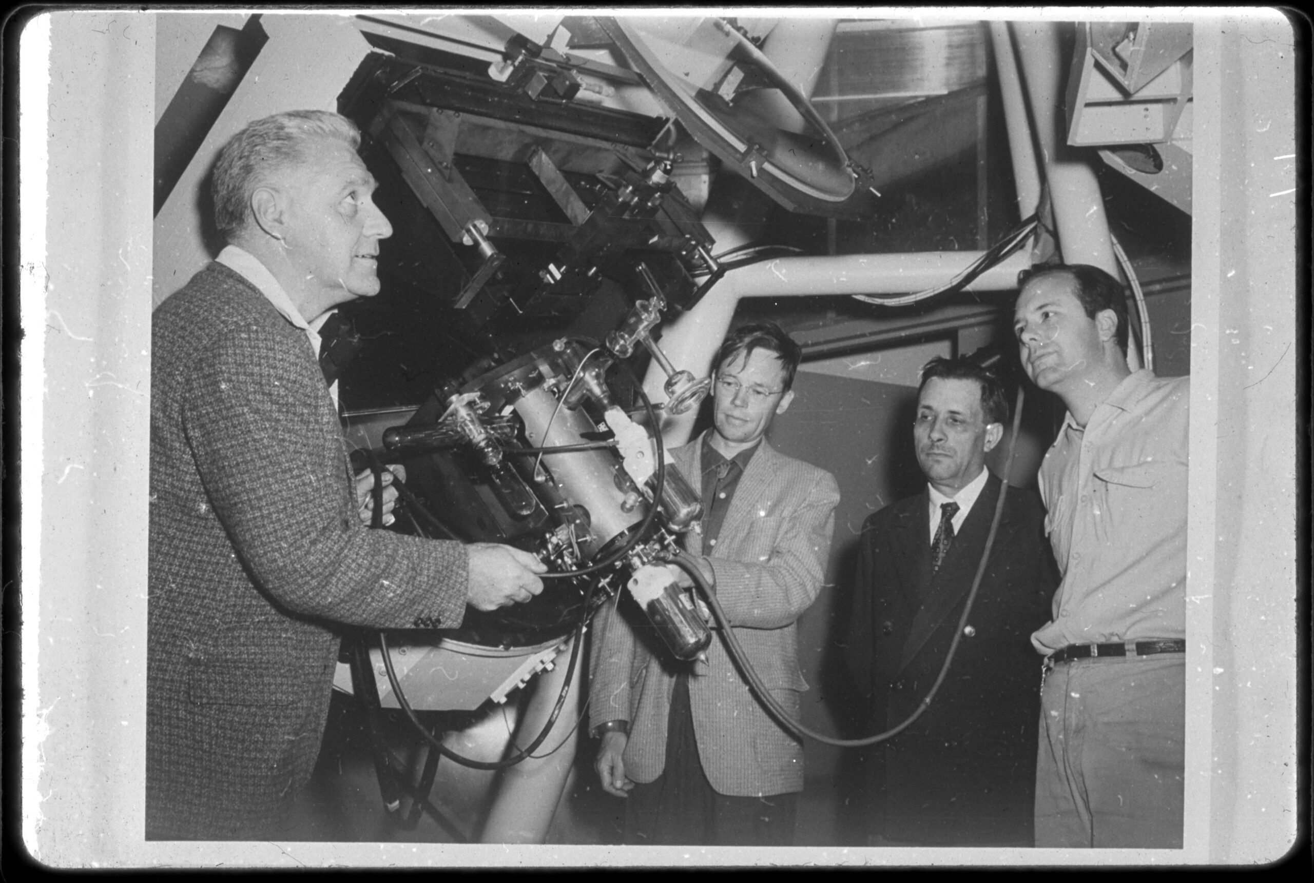
In 1962, French scientist André Lallemand delivered his caméra électronique from Paris to California’s Lick Observatory, where astronomers used the recently developed electronographic device to study the faint features, not just the brightness, of celestial objects. Sixty years later, the staff of the Lick Observatory sent that camera to Washington, DC, to be accessioned into the collection of the National Air and Space Museum. This glass-bodied camera, a metre across and a metre tall, represents the start of an era in astronomy when a community of astronomers and physicists attempted to employ new photoelectronic techniques to develop more efficient cameras for improved observations of two-dimensional objects, in distinction to point source electronic amplification.
Despite the potential of the camera and a surge of initial interest, few astronomers maintained its operation at the observatory. The camera was difficult to operate and required training most astronomers did not have. Regardless of its limited practical use for scientific observations, Lallemand and his camera proved to many that there were technical advances to be made in electronography for astronomy. The astronomical community sought Lallemand’s guidance, as an early producer of the technology, and slowly a network of instrument builders was formed, with Lallemand at its centre. This network included both the instrument makers and users, and while some collaborated across groups, Lallemand maintained his role as camera builder and teacher for those embarking on alternate pathways with the technology. By studying the historic record and by examining the camera, we gain further insight into where Lallemand succeeded and failed in his efforts to aid astronomers. The study reveals the importance of networks in bringing together the required expertise. It also highlights the difficulty in user uptake when those networks do not include collaboration with and consideration for those user groups.
Drawing on physics
Like many experimenting with the growing field of electronics in the early twentieth century, André Lallemand was trained in the physical sciences. In 1925, he was hired as an assistant at the Strasbourg Observatory, where he worked with astronomers Ernest Esclangon (also the Observatory’s director), and André Danjon. Lallemand also worked alongside Gilbert Rougier, a chemical engineer-turned-astronomer, and many physicists in the Observatory’s magnetism laboratory. In 1929, Lallemand accompanied Danjon and Rougier to observe a total solar eclipse and helped capture the first infrared photometry of the solar corona (Danjon and Flammarion, 1930). Through this training and collaboration at Strasbourg, Lallemand gained experience in applying laboratory physics to astronomical pursuits.
Lallemand applied his physics background to astronomy by taking advantage of a major discovery in physics at the turn of the twentieth century: the photoelectric effect, a phenomenon wherein photons of light, as we call them today, when striking certain materials, produce electrons which are more easily manipulated. One practical application came in the form of television technology. In the early 1930s, when the successful development of an all-electronic television system could be read about in every newspaper, André Lallemand first formed an idea for the ‘electronic telescope’. Philo Farnsworth’s image dissector and Vladimir Zworykin’s iconoscope were the first television tubes to be developed, both using photocathodes and an electron beam to transform an optical image into an electronic image that was then displayed on a separate screen to be viewed by the eye (Farnsworth, 1934; Zworykin, 1934). Lallemand proposed a change to this system, whereby the image would be deposited onto an electron-sensitive photographic emulsion rather than a television screen. He hoped this system, where a physical image or spectra was produced, would be more useful to astronomers, who preferred to record and be able to re-examine the data later, an activity far less efficient or quantitatively reliable on a television screen. With the encouragement of Danjon and Rougier, Lallemand began to develop what would become his caméra électronique or the Lallemand camera.
Promoting and developing the Lallemand camera
In 1935, Ernest Esclangon presented the first results from Lallemand’s efforts to the French Academy of Sciences. Esclangon described the device and design, and reported that the sensitivity achieved by the camera was proof of success (Wlérick, 1987, p 168). Esclangon made a specific point to draw attention to the new observations that would be made possible with this tool. A newspaper in Baltimore, Maryland, relayed the story, describing Lallemand’s instrument and pondering whether the new amplifiers would perform well enough to observe Mars closely and settle the debate over whether the red planet hosts life (Anon, 1937, p 48). Lallemand received support from eminent physicists, such as Louis de Broglie and Jean Perrin. With the growing attention, Lallemand continued development efforts at Strasbourg and was promoted to astronomer in 1938. He tested his camera with artificial stars and was pleased with the gain achieved over photography alone, but his work was slowed by the Second World War.
Though he was gaining more recognition, Lallemand would not publish a description of the camera or the results until after the war. In 1943, he accepted a post at the Paris Observatory, a sign of his success and further cementing his role in the astronomical community. In Paris, Lallemand built a laboratory and secured a team with varied expertise, most notably including Gérard Wlérick, helping him improve his camera. After a decade of post-war development effort, Lallemand and his team had designed and built a camera that was tested to great success at French Observatories.
By 1955, awareness of his efforts had spread well beyond the French scientific community. Newspapers reported the new reaches of the universe accessible with the camera. The Liverpool Echo noted that Lallemand’s camera could perform like a telescope 100 times bigger than the largest telescope, at Mount Palomar (Anon, 1951, p 3). An American newspaper noted that ‘Two French scientists have developed an electronic camera which they say should enable them to “see” 10 times farther into the universe than man has ever before’ (Anon, 1955, p 70). Journalists in South Africa wrote ‘with the new device tacked on to it, astronomers believe that Saint Michel’s telescope will become even more powerful than the giant 200-inch telescope on Mount Palomar in California’ (Pastore, 1955, p 321). Lallemand’s successes made the application of television technology towards scientific endeavours a promising pursuit.
Alongside the growing public awareness came an increasing interest from astronomers. While the war slowed down the development of Lallemand’s camera, it also led to a growing number of astronomers with training in electronics. Students engaged in postdoctoral work and astronomers early in their careers had their research suspended and refocused on military efforts, notably the development of infrared-sensitive photoelectronic detectors. After the war, there was an increase in the interest and ability of observatories to use electronic instruments, such as photomultiplier tubes which allowed an increase in sensitivity of point-source measurements in visible, infrared and ultraviolet wavelengths. The Carnegie Observatories, Washburn Observatory and Lick Observatory now had several astronomers on staff who were experienced in electronics and were avid supporters of expanded use. In 1953, the National Science Foundation hosted a conference on photoelectric photometry at Lowell Observatory in Flagstaff, Arizona, with 35 astronomers in attendance, representing all the major observatories in the United States, including Lick Observatory. In 1958, Imperial College London hosted a symposium on photoelectronic image devices. A clear, growing community was developing, eager to apply photoelectronic techniques in astronomy, and that community began to seek connections, in pursuit of those with expertise. Astronomers contacted television companies, those with proven electro-optical capabilities, and Lallemand, who had first published a successful application to astronomical pursuits.
Developing a network of instrument builders and maintainers
New hubs of development appeared where astronomers and physicists worked together to design photoelectronic cameras for astronomers, including the Carnegie Observatories, Lick Observatory, Washburn Observatory, Lowell Observatory, Imperial College of Science and Technology and the Royal Greenwich Observatory. Those at these observatories and laboratories first encouraged and supported the ongoing development of the image tube, the general name for all types of two-dimensional photoelectronic camera. At major firms, those typically engaged in the production of television tubes but who had an interest in expanding their user base, found that their efforts could not satisfy the extreme low-light level needs of astronomers. Throughout the 1950s, as Lallemand’s work expanded, other astronomers, most notably in France, Britain and the United States, invited Lallemand to visit and consult on their interest in developing photoelectronic capabilities at their home observatory. Through this travel and collaboration, a network of instrument builders emerged.
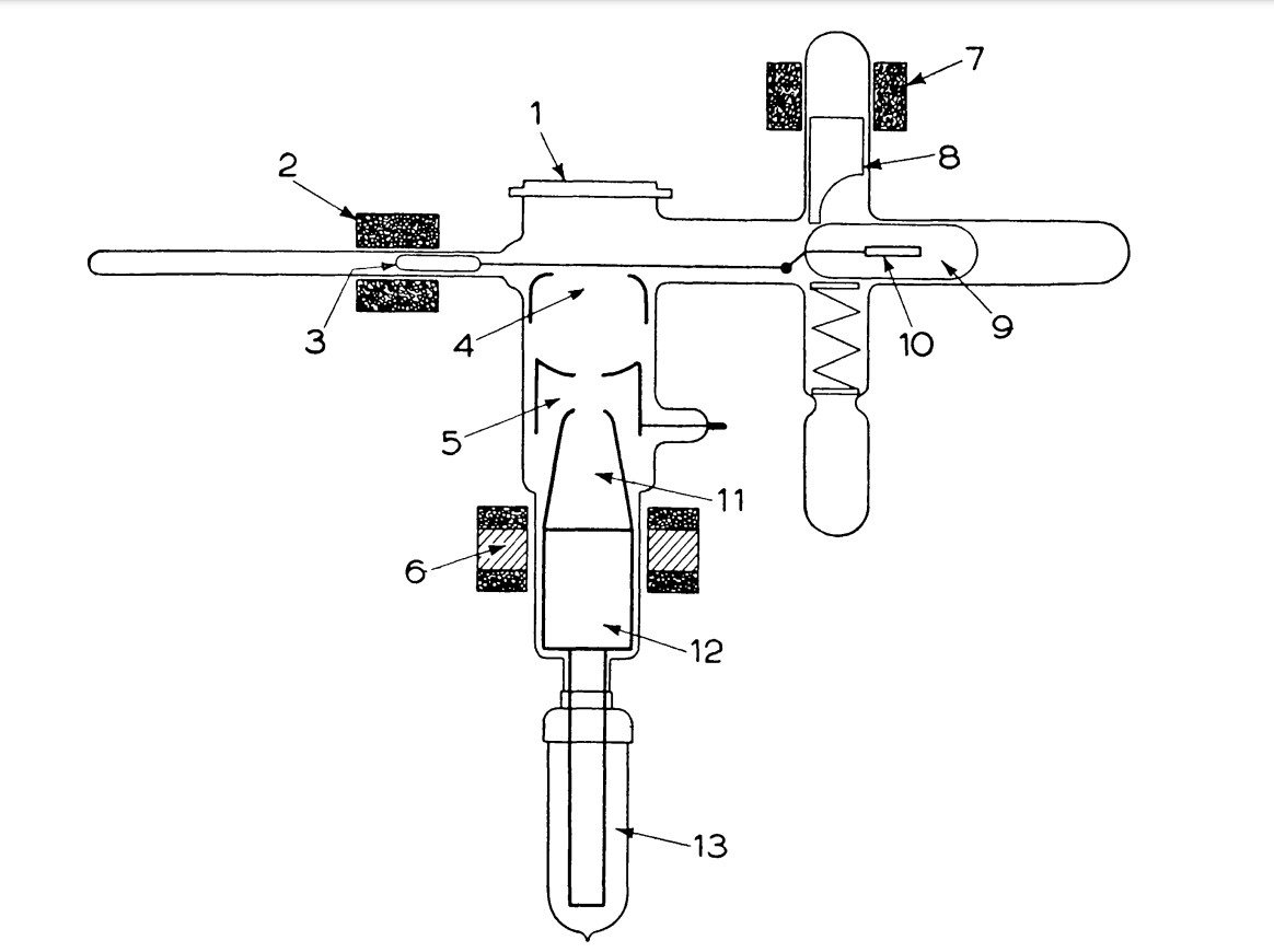
In 1955, Lallemand visited many universities and observatories to instruct on the operation of his camera, but many feared that his device was too complicated for most astronomers to use. Lallemand’s camera consisted of a glass enclosure containing a photocathode, an electrostatic focusing system, and an electron-sensitive plate cartridge. Many potential users thought a primary weakness was the camera’s complicated operation, which required that the observer carry out a complex series of procedures before it could be attached and used at the telescope. Before each evening’s observing run, astronomers first had to prepare the photocathode. After careful cleaning and sealing, followed by removing all air from the camera, the astronomer had to position a glass ampoule that contained the photocathode over the electron optics. In order to retrieve the data off the photographic emulsion, the astronomer had to break the glass ampoule and destroy the photocathode. To conduct another observation, a new photocathode needed to be prepared, each taking a full day of work. The results obtained with the Lallemand camera provided more contrast and better sensitivity, but the cumbersome preparation and operation prevented many from using the device (Somes-Charlton, 1959, pp 417–435).
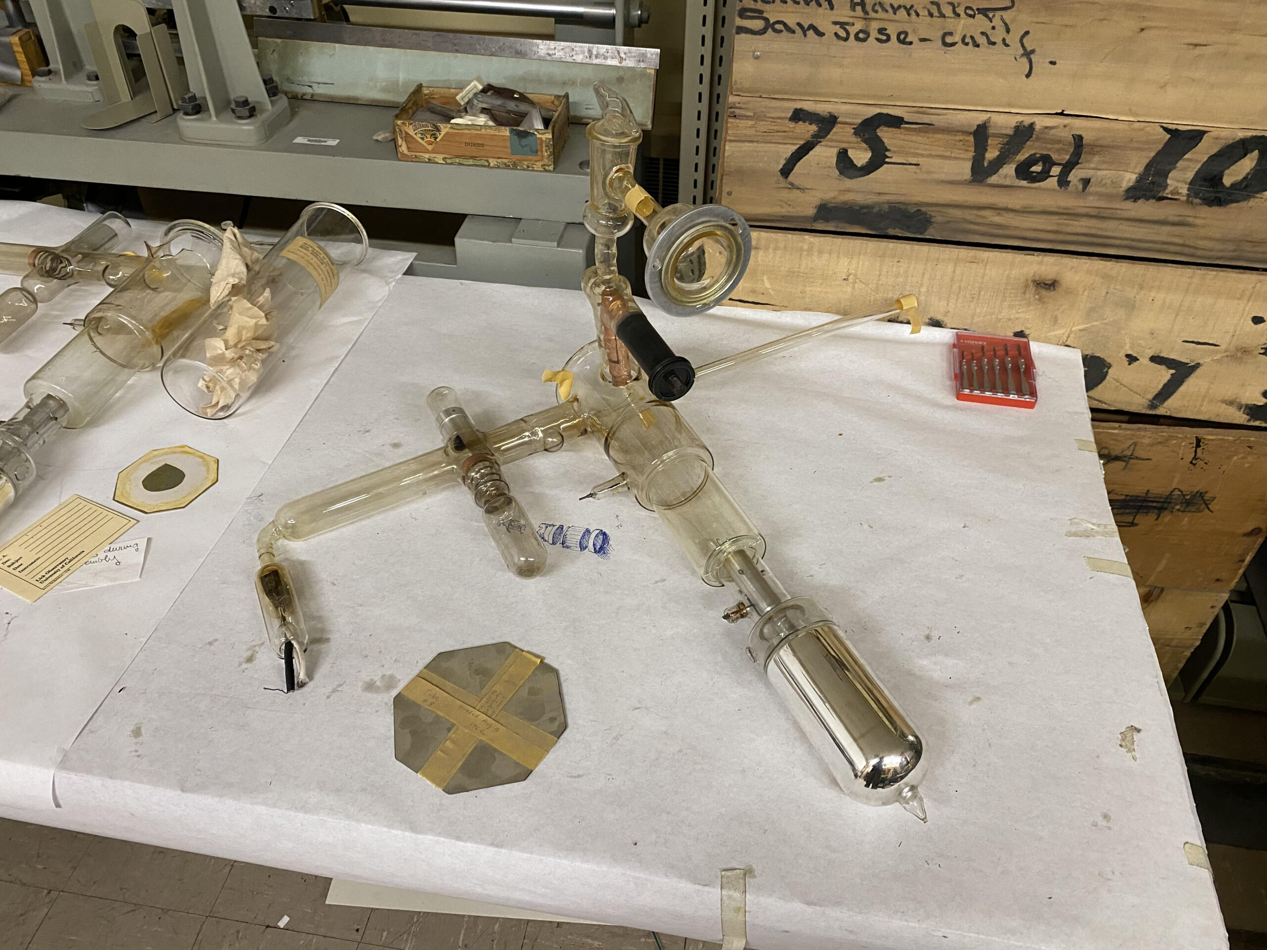
The operation required by the Lallemand camera and similar instruments was an obstacle too difficult to overcome for many observers. Its impracticality can still be seen today. The 32-page typed user’s manual and the delicate glass contraption with its many electronic parts needing reassembly after shipment were far less user-friendly than the standard photographic camera. The hand-blown glass varies in thickness, making it more prone to breakage. Lick Observatory astronomer Merle Walker later recalled that they had to employ local glass workers to fix cracks, a process that still needs to be performed to ensure the conservation of the remaining Lallemand cameras.[27] Though a few astronomers, like Walker of Lick Observatory, used the device with some success, attracted by its increased sensitivity over photography alone, it did not gain wide acceptance because of the practical difficulties associated with its use.
Though there was a marked increase in the number of astronomers who could operate electronic equipment, most observers required an assistant to help, which few were accustomed to or economically able to support. It therefore became more difficult to convince some astronomers to take on a task that they did not have sole responsibility over. This became an even greater hurdle when others, advised by Lallemand, were developing image tubes that were easier to use or in closer collaboration with astronomers (Thompson, 2019). Merle Tuve, director of the Carnegie Institution Department of Terrestrial Magnetism, wrote to one astronomer contending that, ‘If we supplied you or your colleagues with a Lallemand tube, with sealed-off cassettes of fresh cesium surfaces, I am confident its best use would be as an exhibit on the Observatory shelves’.[28] Most observatories concluded that they needed to develop their own device that was simpler to operate, making it more appealing to a wider group of users.
The developers shared information within the astronomy community and across to other fields in television, chemistry, medicine, and toward military goals, but this network typically only included the instrument builders. Imperial College London’s symposium on photoelectronic image devices, encompassing ten meetings from 1959 to 1991, served as a hub of community networking and engagement for three decades, but its attendees were the developers of technology and rarely those who were solely its users (Thompson, 2019, p 121). Since Lallemand’s camera had first been proposed in the 1930s, astronomers not actively involved in development efforts expected progress to have advanced more than it had but, even without a clear alternative, few were inclined to take on the difficult operation of the new device. Once simpler devices were created, some users tested the new cameras, but uptake was still low, a sign that the needs of astronomers were not fully considered when designing the new instruments.
A network failure?
Lallemand’s camera received its most frequent use in France, where Lallemand could more readily advise. In the United States, it was used most at California’s Lick Observatory, which donated one of their two remaining Lallemand cameras to the National Air and Space Museum in 2022. In 1959, Merle Walker and Gerald Kron of Lick Observatory invited Lallemand to bring a camera to attach to their new 120-inch telescope, the second largest telescope at the time. With the aid of Lallemand and his colleague Maurice Duchesne, they recorded spectra from the core of the Andromeda galaxy. This data showed that the core was a distinct entity, rotating 100 times faster than the rest of the galaxy, a major accomplishment in astronomy. With a Lallemand camera, Lick Observatory astronomers observed these galaxies and helped provide further evidence for the existence of black holes at the centre of galaxies. The Lallemand camera was used successfully, obtaining extraordinary results, for over a decade at Lick Observatory, but few other astronomers at Lick attempted to operate the device.
Lallemand retired from active scientific life in 1974, but his cameras were last used in the 1980s, on the Canada-France Hawaii Telescope on Maunakea. The development of the charge-couple device (CCD) in the 1980s eventually overtook the prior technology and development efforts decreased rapidly. Though the community that existed to aid development of photoelectronic imaging devices was broad in scope and dedicated, with Lallemand as an early supporter and liaison, the technology failed to succeed in replacing photography alone as the primary means of astronomical recording.
For an idea that first emerged in the 1930s, relatively little uptake of image tube technology could be found after fifty years of development. This was not for lack of effort by instrument builders, who had formed a network that expanded beyond astronomy. Lallemand’s background was similar to that of others he collaborated with, who had first investigated image converters (television-like tubes that had the ability to detect infrared light). Like Lallemand, they combined their background in physics with a growing interest in astronomy to develop new photoelectronic techniques. The reason why the technology was not taken up by more astronomers is complex and is largely due to users not being fully involved in the development process, leading to the instrument makers not fully appreciating the limitations of the observers. The difficulty of operation remained a frequent challenge, leaving few willing to change their observational practice.
The Lallemand camera transferred by Lick Observatory to the National Air and Space Museum will serve as a visual reminder for museum visitors of the challenges and successes of this technology and of the importance of instrument makers in astronomy. It will also highlight the special requirements of astronomical observations. Conservation challenges are unique when handling and displaying an object with a long history of breaking, but the frailty of the artefact is a major and important part of its story. The camera will be displayed, with optical elements preserved inside, as an example of the effort some astronomers took to further their scientific understanding of the universe. Lick Observatory astronomers persisted through the difficulties of the camera because it gave them a closer look at the motion at the centres of galaxies. Ultimately, the story of the artefact is one of both technological development and scientific discovery.
Tags
Footnotes
References
Authors

Media in article