Writing sound with a human ear: reconstructing Bell and Blake’s 1874 ear phonautograph
Article DOI: https://dx.doi.org/10.15180/191206
Abstract
Museums collect, preserve and interpret physical objects because they contain historical evidence that is sometimes difficult – if not impossible – to access through text and image-based research alone. In cases where original objects have been lost to history, reconstructions offer one way of reclaiming aspects of a past object’s design, use context and material culture. This article describes one such reconstruction project, which I recently undertook with collaborators at the Canada Science and Technology Museum in Ottawa. The goal of the project was to reconstruct Alexander Graham Bell and Clarence J Blake’s ear phonautograph: an 1874 curiosity that used an excised human middle ear to visually inscribe sound waves. Originally conceived of as a tool for deaf education, it became better known as the instrument that provided Bell with the technical insights he needed to develop and patent the telephone in 1876. This article consists of three parts. The first provides a historical background of the ear phonautograph and rationale for its reconstruction; the second offers a detailed description of the research and fabrication process; the third presents preliminary research findings that emerged through our experience building and operating the completed reconstruction.
Keywords
acoustic science, Alexander Graham Bell, Clarence J Blake, ear phonautograph, reconstruction, sound technology, telephone origins, visible speech
Introduction
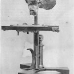
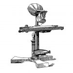
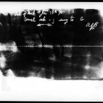
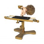
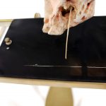
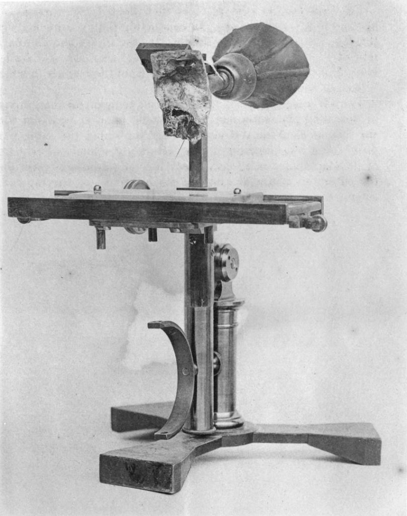
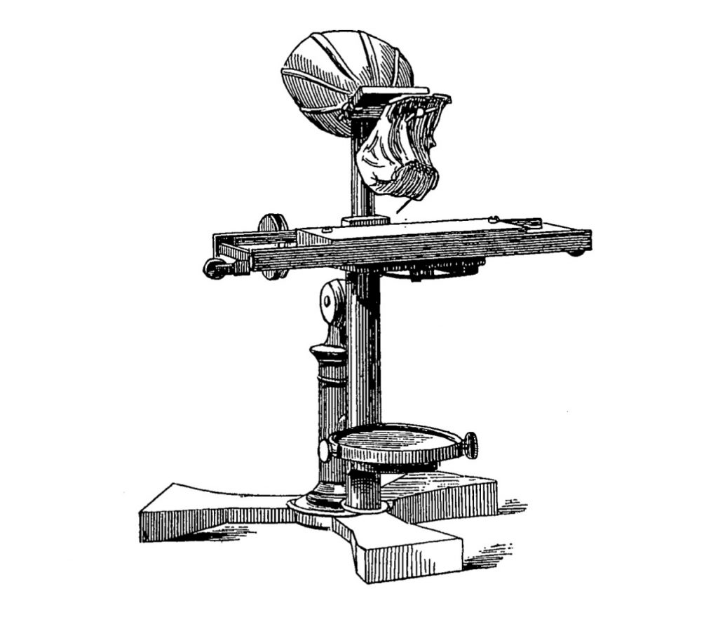
https://dx.doi.org/10.15180/In 2016, I embarked on a collaborative project to reconstruct a peculiar sound-writing instrument called the ear phonautograph. Built in 1874 by Alexander Graham Bell and Clarence J Blake, the ear phonautograph used an excised human middle ear to transform invisible sound waves into visible etchings observable on a plate of smoked glass.[1] It worked by channelling sound wave vibrations, produced by speaking into the mouthpiece of the instrument, into the auditory canal of the ear. This in turn caused a stylus, attached to the ear drum’s ossicle bones, to similarly vibrate. When a plate of glass – smoked with soot from an oil lamp – was pulled quickly underneath the stylus, the speech vibrations were etched as a continuous waveform across its surface. This etching could then be ‘read’ by the speaker to determine the shape or pattern that the speech vibrations produced (see Figures 1–3).
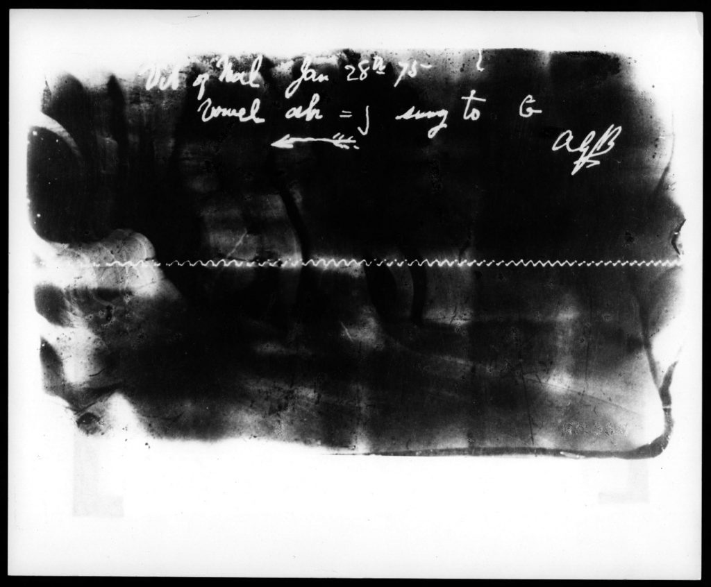
The ear phonautograph was inspired by Édouard-Léon Scott de Martinville’s original phonautograph, or sound-writer, first introduced in 1857.[2] Scott de Martinville felt that an instrument that ‘would reproduce by a graphic trace the most delicate details of the motion of the sound waves’ (Scott de Martinville, 1857: trans. by Feaster, 2010, p 7) could contribute greatly to the preservation and scientific study of sound.[3] To solve the problem of how to model such an instrument from available acoustical technologies, he reasoned that he could do no better ‘than to copy in part the human ear, in its physical apparatus only, adapting it for the goal I have in mind’ (Scott de Martinville, 1857: trans. by Feaster, 2010, p 7, original emphasis). For several years, Scott de Martinville experimented with natural materials like goldbeater’s skin and boxwood to best approximate the human ear drum (tympanic membrane) and ossicle bones.[4] What made Bell and Blake’s ear phonautograph unique is that it went a step further by using an actual human ear as the tympanic mechanism at the centre of the instrument.[5] They felt that the sensitivity of a biological ear would enable their phonautograph to respond even more accurately to sound wave vibrations, and thereby produce more precise visual sound etchings, than was previously possible.[6] This improvement was desirable for a project Bell was working on with his father at the time called ‘visible speech’, which involved employing various visualisation techniques to teach the deaf how to speak.[7] Bell felt that a more precise sound-writing instrument would allow his deaf students to clearly see what certain vowels ‘sounded’ like, and thereby improve the clarity of their speech by comparing a hearing person’s etchings to the etchings they themselves produced by speaking into the machine.[8]
What first piqued my interest in the ear phonautograph was not its use in visible speech – by all accounts a short-lived and ultimately failed enterprise – but its role in the historical development of the telephone.[9] As Bell claimed in the years following his successful telephone patent application in 1876, it was in studying the relationship between the tympanic membrane and ossicle bones in the ear phonautograph that he gained the technical insight he required to invent the telephone. ‘While engaged in these [ear phonautograph] experiments,’ he wrote in 1877,
I was struck with the remarkable disproportion in weight between the membrane and the bones that were vibrated by it. It occurred to me that if a membrane as thin as tissue paper could control the vibration of bones that were, compared to it, of immense size and weight, why should not a larger and thicker membrane be able to vibrate a piece of iron in front of an electro-magnet.
Soon after this realisation, Bell refocused his efforts toward devising a means to convert sound wave vibrations into electrical impulses. This, he correctly hypothesised, would finally make long-distance speech communication possible by wire.[10] Blake continued to experiment with the ear phonautograph for several years independently of Bell, but he too eventually moved on to new projects and the instrument was largely forgotten. Today the ear phonautograph remains a relatively unknown footnote in the early development of the telephone, and no one has reported seeing the object since.[11]
It was during the process of developing a new permanent sound technology gallery at the Canada Science and Technology Museum that the idea for an ear phonautograph reconstruction came about. As curator of this gallery, called Sound by Design, I felt a display on the ear phonautograph could open up new and important conversations about the origins and politics of Bell’s early work.[12] While the prospect was compelling, it immediately presented the problem of what might be included in this display. Since the ear phonautograph is presumed lost to history, we had no choice but to rely on two-dimensional imagery – specifically, two surviving images of the instrument (Figures 1 and 2) – to serve as our visual anchors for the display. We found this approach dissatisfying, however, because it seemed to undermine our guiding artefact-based vision for the gallery. If we were to include a display on the ear phonautograph, our team agreed that it needed to be given the same material weight as the other displays encountered throughout the space. We briefly pursued the possibility of acquiring a loan from the Smithsonian – keepers of the only known previous ear phonautograph reconstruction effort – but soon abandoned this option based on the lack of provenance of the object, its imperfect visual approximation to the original instrument, and the high cost and short duration of the loan. After much deliberation, we opted instead to pursue a riskier but also potentially more rewarding option: attempting a reconstruction of our own. We hoped our reconstruction would not just contribute to a more compelling visual display, but to borrow the words of museum scholar and reconstruction practitioner Doron Swade (2011, p 125), ‘act as a nucleus of visitor attention, define the boundaries of historical discourse, and stimulate new questions and new lines of thought’ about this historic instrument.
There were two other reasons I was keen to undertake this reconstruction project, beyond securing a three-dimensional object to use in our gallery display. First, I wished to test a theory that the process of building a reconstruction would itself serve as a knowledge-generation exercise capable of providing unique insight into the ear phonautograph’s design and material culture. Following other reconstruction and re-enactment practitioners such as Elizabeth Cavicchi (2003), Peter Heering (2008), and contributors to Klaus Staubermann’s edited volume Reconstructions (2011), I was interested in seeing what unexpected observations we might make, by actually building the instrument, that might not otherwise be gleaned from primary and secondary source texts alone.[13] A second theory I wished to explore, further supported by the above authors, was that additional knowledge would be gained by going a step further and actually operating the instrument. To satisfy this operational requirement, we decided to make every effort to not just create an accurate visual approximation of the ear phonautograph – which alone would have been enough to satisfy our primary gallery needs – but also to restore, as much as possible, its original functionality. The remainder of this paper outlines the process and research findings generated by this reconstruction project.[14]
The first section outlines the major steps involved during the fabrication phase. This involved experimenting with various textual and artefact-based research strategies to answer questions pertaining to the ear phonautograph’s material construction, design and functionality. This knowledge was then applied to fabricating the four main components of the instrument: the main structure, mouthpiece, moving glass assembly, and tympanic apparatus. The phase concluded with revisions to our initial prototype, which were made to bring it more closely in line with the appearance and functionality of the instrument as described in Bell and Blake’s early research reports (1875; 1876; 1877).
The next section then describes preliminary research findings that emerged through our experience building and operating the completed reconstruction. One of our most significant findings was that the original ear phonautograph was not entirely custom-made, but was instead fabricated on a pre-existing microscope structure. This discovery helped settle existing uncertainties about the material construction and functionality of the original instrument, while also providing insight into the process and historical context in which it was made. Specifically, it shed light on a kind of ‘hacker’ sensibility that undergirded the ear phonautograph’s technical development, as evidenced by Bell and Blake’s decision to creatively modify a pre-existing technology to achieve a different set of outcomes rather than build an entirely new instrument from scratch.[15] As we set about testing the completed reconstruction, we also discovered certain elements in the pre-existing microscope structure that were indeed essential to the instrument’s successful operation. This solidified the ear phonautograph’s status as an important point of contact between the dominant observational paradigm that informed its initial development – characterised by a desire to objectify scientific knowledge by rendering the invisible visible – and the acoustic paradigm it helped pave the way for by inspiring the invention of the telephone. Perhaps equally significantly, we were able to affirm that the practice of reconstructing historic objects remains highly valuable and rewarding for historians and museum professionals hoping to uncover new knowledge that might otherwise remain buried deeply between the lines of existing textual records.
I would be remiss to proceed further without naming several individuals whose contributions were essential to the successful realisation of our reconstruction effort. Denis Larouche was the lead designer and fabricator on the project, and it was his dedication and technical abilities that gave us reason to believe that a reconstruction of the original ear phonautograph was indeed possible. All due credit for the instrument’s final design and fabrication go to him. Serge Duguay, project manager, and Britt Braaten, interpretive planner, played key roles in the conceptualisation and execution of the reconstruction – particularly in terms of its eventual display in the Sound by Design gallery.[16] Jessica McEwan and Isabelle Castonguay of the University of Ottawa Health Sciences Library provided immeasurable support by producing the 3D print of the human middle ear that was essential to our ability to complete the final instrument. Finally, Kyle Devine, Ainslie Coghill, Ming-Yuen S Ma, and two anonymous readers contributed valuable insight into the interpretation and research outcomes of the project by providing comments and constructive feedback on earlier versions of this paper.
Reconstructing the ear phonautograph
https://dx.doi.org/10.15180/191206/002I. Building the base structure
The first step in our reconstruction project was building the ear phonautograph’s main structure. To ensure a high degree of historical accuracy throughout this and the rest of the fabrication phase, we relied predominantly on primary research documents for clues pertaining to the instrument’s possible size, shape, material construction and functional characteristics. The most important primary source texts available to us were two research reports written by Blake pertaining to the fabrication and operation of the ear phonautograph (Blake, 1875; Blake, 1876), and one report written by Bell articulating the significance of the instrument in relation to his work on the telephone (Bell, 1877). These documents included descriptions of various components of the instrument – from the design of mechanisms controlling the movement of the smoked glass plate, to the preparation of the sensitive middle ear components and stylus, to the mechanical operation of the final instrument. They also included two images – one photograph published by Blake (1876) and a line drawing published by Bell (1877) – that provided us with a close visual approximation of what our reconstruction should look like once it was completed (see Figures 1 and 2).[18]
For all the detail present in these reports, one of the first surprises we encountered in attempting to fabricate the ear phonautograph’s main structure was how little information was provided on its material construction. Even in Blake’s reports – which devoted many pages to describing minute details, such as how the ear specimen should be excised and prepared to achieve the best possible phonautographic outcome – no information was provided as to how to actually replicate the main structure upon which this and the other components were affixed. This meant that educated guesswork was necessary to determine exactly what materials to use in our structure, how each element should be fabricated and assembled, and how each component should then be arranged in order to recreate the instrument’s original functionality.
To fill in the gaps left by these primary source texts, we decided to pay a visit to the Canada Science and Technology Museum’s permanent artefact reserves to see if other scientific instruments, manufactured during the same historical period (c. 1870s), might offer clues as to the possible materials and design principles Bell and Blake may have applied in building their instrument. Of those we consulted, a collection of microscopes immediately stood out as having a close resemblance to the ear phonautograph’s main structure. Some common elements included a three-pronged base, two-part cylindrical stem, rectangular staging assembly, and machined brass finish. The resemblance was so uncanny, in fact, that we began to wonder if the ear phonautograph’s base structure might actually be a microscope that was modified by Bell and Blake to achieve a different functionality.
Upon closer inspection, we found compelling evidence to support this idea. Located on the lower stem of each of the microscopes was a small circular mirror that would have been used to reflect light upwards through the bottom of the glass stage for the illumination of microscope slides. An identical mirror is clearly visible in Bell’s line drawing of the ear phonautograph, as is an empty semi-circular bracket in Blake’s photograph that would have at one time been used to house such a mirror. This strongly suggested that Bell and Blake had not had their instrument custom-machined, but had instead simply borrowed a common microscope and adapted it to suit their purposes: namely, by removing the upper ocular components, and introducing new elements that would permit the structure to function suitably as a phonautographic apparatus. Incidentally, we were surprised to learn – upon doing keyword searches shortly after making this discovery – that we were not the first to notice this similarity. An article published by Charles Snyder in 1974 on Bell and Blake’s research collaborations includes an off-hand remark that ‘[t]he whole affair [the ear phonautograph] was mounted on a microscope stand’ (pp 12–13). Whether Snyder arrived at this conclusion independently, through a close examination of surviving images of the ear phonautograph, or by some other means is impossible to say, for he offers no evidence or additional commentary to support this claim. Regardless, our preliminary material investigation suggested that he was most likely correct in making this assumption.
Rather than fabricate a new microscope stand ourselves, we decided to acquire a period (c. 1870s) microscope to serve as the main structure of our reconstruction. This, we reasoned, would have the dual benefit of increasing the historical accuracy of our build while also ensuring that we wouldn’t inadvertently overlook any of the functionalities contained within the original microscope that might bear some hidden significance to the ear phonautograph’s operation. We estimated the size of the microscope based on approximate measurements of a human middle ear – our only reliable dimensional reference point – and proceeded to visit antique dealers and monitor local classified ads to source an instrument suitable for our build. We eventually located and purchased an ideally-sized microscope on eBay, which our designer then prepared for use in the reconstruction by dismantling the upper ocular portion of the instrument and removing all extraneous components that didn’t appear to match up with the images provided in Bell and Blake’s reports. We then set to work determining which additional components would need to be added to the base structure in order to complete its conversion into a functional phonautographic instrument. Of these, we decided to proceed first with the mouthpiece and moving glass assembly.
II. Constructing the mouthpiece
From Blake’s descriptions, it seemed clear that the purpose of the ‘bell-shaped mouth-piece’ (Blake, 1876, p 112) was relatively straightforward: to collect sound waves produced by a human speaker, and then funnel these sounds into a tube leading directly into the auditory canal of the excised middle ear. Disappointingly, as with the main structure, neither Bell nor Blake’s reports offered any concrete information about what the mouthpiece was made of, nor any clues as to where or how it may have been acquired. Based on our previous microscope discovery, we hypothesised that the mouthpiece too had likely not been custom-made, but had instead been borrowed from another pre-existing instrument. To determine exactly which instrument it may have come from, we returned to the Canada Science and Technology Museum’s artefact reserves to examine a selection of late nineteenth century wax cylinder phonograph and dictation machines that appeared to employ similar bell-shaped mouthpieces. Unfortunately, this investigation proved inconclusive. We were unable to locate any mouthpieces with a similar shape and finish to the one depicted in Bell and Blake’s images, and were left with no alternative but to guess what the mouthpiece was made of and set about fabricating it ourselves.
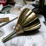
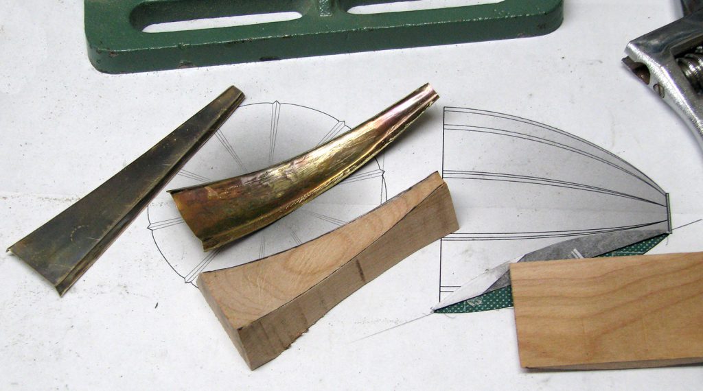
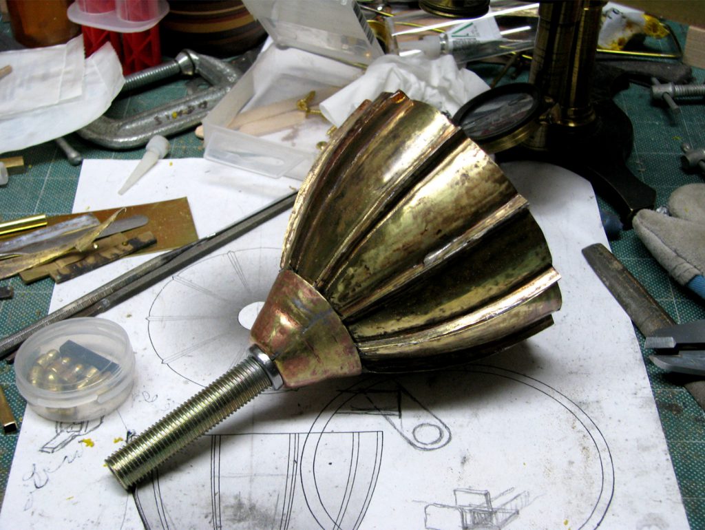
Our designer proposed fashioning the mouthpiece out of thin brass strips, which he felt would best approximate the look and finish of the mouthpiece as depicted in our reference images. This material would also provide maximum flexibility in terms of how it could be cut and coloured, and had the additional benefit of not adding too much additional weight to the overall structure. Once this was agreed upon, he set about preparing ten brass strips which were then hammered into shape and soldered together to form the requisite bell shape of the mouthpiece (see Figure 4). To the narrow base of the mouthpiece, he then affixed a short cylindrical steel rod that would serve to funnel sounds directly from the mouthpiece into the ear canal of the middle ear specimen once it was completed (see Figure 5).
III: Constructing the moving glass assembly
The construction of the moving glass assembly was in some ways less complicated than the structure and mouthpiece, as Blake offered considerably more information on its fabrication and function. Its purpose was to translate physical vibrations from the stylus into a continuous visible etching on a moving plate of smoked glass. The assembly consisted of four main components: a smoked glass plate (to record the etching), a carriage (to carry the glass plate), a flat rectangular stage (to provide a surface for the carriage to glide across), and a pulley system (to ensure the glass plate maintained an even pace as it passed beneath the stylus).
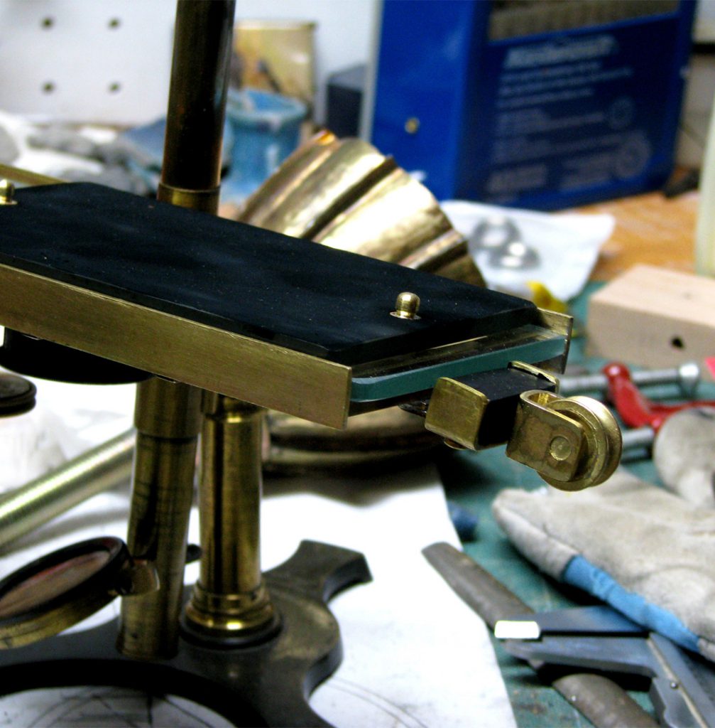
Despite the high level of detail present in Blake’s descriptions of the moving glass assembly, we quickly discovered inconsistencies in his descriptions that needed to be resolved before the build could comfortably proceed. For example, in his earlier (1875, p 122) description of these components, he describes ‘a metallic stage six inches in length, upon which slides a metal carriage carrying a glass plate’ (my emphasis). In his later (1876, p 112) description, he instead describes ‘a metallic stage having a glass bed six inches in length, upon which slides a glass carriage carrying a glass plate’ (my emphasis). Without knowing which report represented the most accurate description of the instrument, we opted to follow Blake’s latter instructions and build a brass stage with a glass bed, which we felt would provide a smooth and abrasion-free surface for the smoked glass plate to glide across. With respect to the carriage and plate components, we were perplexed as to why the smoked glass plate would require a carriage at all – be it metal or glass – as a glass plate alone could easily achieve both functions. Perhaps the goal of the carriage was to make the glass plates easier to prepare and change out, as only the carriage would require holes to be bored into its surface to permit the plate to be pulled across the stage (see next paragraph). Since Blake offered no additional information to clarify the design or purpose of this element, and since it was unclear in the surviving images of the ear phonautograph where the carriage ended and the plate began, we opted to forgo the construction of a separate glass carriage and instead use a single piece of glass that would act as both carriage and plate. This would simplify the build for testing purposes while also reducing the complexity of the instrument’s operation since only one component would need to be in motion at once.
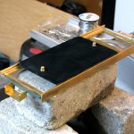
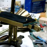
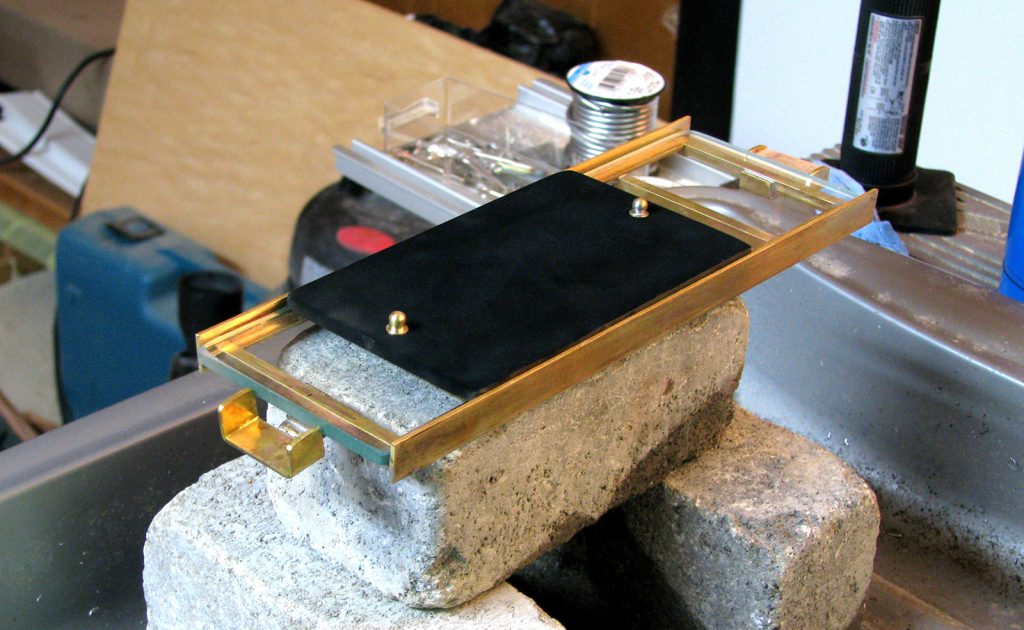
Once the glass plate was cut and ready for installation, our designer proceeded to bore two holes through the top of each side and insert two metallic nubs that could be used to pull it horizontally across the stage. This pulling action could be achieved by hand, or alternatively – as Blake (1876, p 112) suggested – by tying a cord with a weight attached to one of the nubs, and then threading the cord through a pulley installed at the edge of the stage. When the weight was dropped, the pulley would ensure the moving glass plate would maintain an even and uniform pace for the duration of its glide across the stage.[18] To preserve this function, our designer fabricated a similar pulley system – clearly visible in both surviving images of the instrument – and sourced an appropriate cord made of linen thread that could be used for further experimentation. He then proceeded to smoke the top of the glass plate with soot from a candle’s flame and place the plate on top of the glass-bedded stage, where it would be poised to receive etchings once the tympanic apparatus was completed (see Figures 6 and 7).
IV. Fabricating the tympanic apparatus
Once the mouthpiece and moving glass tray assembly were completed and affixed to the main structure, the final step was figuring out what to do about the most iconic piece of the puzzle: the human middle ear. Although we were committed to producing the instrument with as much faithfulness to the original as possible, we had serious concerns about obtaining a real human specimen for use in our reconstruction. For one, the ear was – and remains – one of the most controversial aspects of the original instrument. To date, nobody has been able to say for certain who was ‘the true hero – a specimen of a human ear – donor unknown’ (Snyder, 1974, p 3), though the ear(s) were likely acquired without prior consent and by potentially dubious means (see Sterne, 2001; Ma, forthcoming 2020).[19] Blake himself was opaque on the issue, stating only that the ‘membranes employed in [our] experiments have been preferably those of the human subject, as being most readily obtainable under favourable conditions’ (Blake, 1876, p 110). Interpreted historically, this statement becomes both problematic and unsettling. As Ming-Yuen S Ma writes:
I can find no information on the race of the body that provided the ears for the ear phonautograph, but given the historical conditions, their provenance is likely from an executed criminal, or a poor person whose body was unclaimed. Perhaps they were from a black man or woman whose grave was robbed? Or perhaps all of the above?
Jonathan Sterne remarks that Blake’s ‘casual attitude toward the ears in the phonautograph likely came from his professional milieu’ (Sterne, 2001, p 271), in which the acquisition of bodies for experimentation and research purposes was considered the norm. By contrast, anecdotal evidence suggests that Bell may have been more self-conscious – if strategically so – about how the public might respond to the uncomfortable realities surrounding their instrument:
…the strangeness of carrying around a machine consisting in part of a human ear was not lost on its inventors. As was Bell’s practice, he spent the summer of 1874 with his parents in Brantford [Canada]. Bell brought his machine with him, and word quickly got around the town that he had a machine with a dog’s ear or a pig’s ear affixed to it. One biographer (Snyder, 1974, p 13 ) speculates that Bell himself propagated these rumours in order to prevent gossip about a human ear.
Beyond historical concerns, there were also questions about whether we could ethically justify acquiring a real human ear for our own experimental purposes. Or indeed, whether absolute verisimilitude to the original ear phonautograph was even necessary to obtain sufficient knowledge about its design and functionality. As an alternative, we briefly considered the possibility of substituting the human ear for the ear of a deceased animal, sourced from a local slaughterhouse. But even here, ethical and practical questions remained. In particular, we were concerned about our ability to procure and adequately prepare an appropriate specimen, to ethically justify and interpret this modification to the original ear phonautograph’s design for museum visitors, and to ensure the long-term exhibition and preservation of a specimen composed entirely of sensitive biological tissue. So rather than employ a biological ear in our reconstruction – human or animal – we decided to instead experiment with modern materials to best approximate its desired appearance and functionality. We reasoned that much had changed in the development of synthetic materials over the last hundred and fifty years, and so by taking advantage of these materials we might fabricate an artificial ear that could approximate both the visual appearance and mechanical operation of a real human ear, while also making it easier to display and preserve.
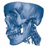
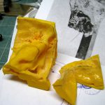
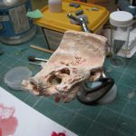
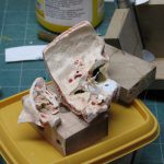
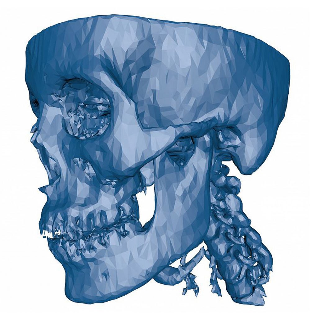
To achieve this compromise, we reached out to the University of Ottawa Health Sciences Library for help. We hoped that their experienced technical staff might assist us with producing a biologically accurate facsimile of a human middle ear that would be suitable for our reconstruction. After several consultations, they suggested the best approach would be to digitally ‘excise’ the portion of the ear we required from a 3D scan of a real human skull, which could then be printed using a 3D printer. We felt this approach was ideal, and so library technician Isabelle Castonguay set to work producing a plastic 3D print from a 3D scan found in the US National Institute of Health’s open-source 3D Print Exchange (see Figures 8 and 9).[20]
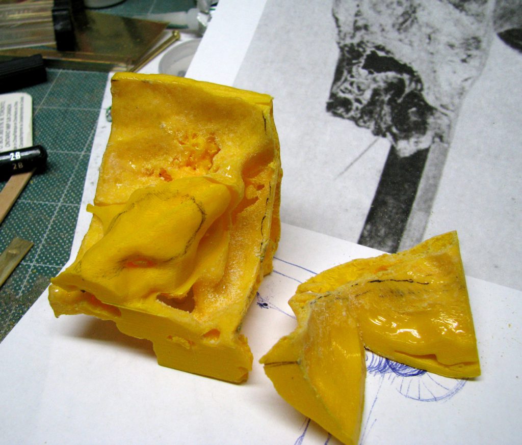
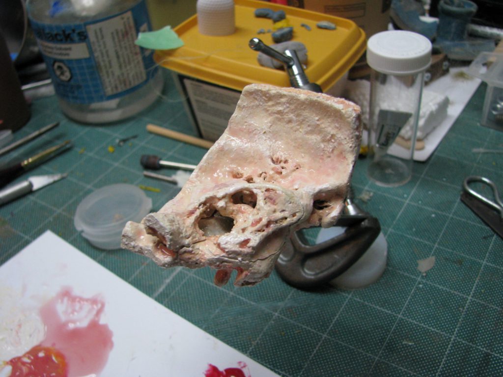
Once the print was completed, our designer then customised the ear by trimming and sanding down the edges to achieve a closer visual approximation to the ear pictured in our reference images, and then painting it to resemble real human bone tissue (he used a beef soup bone to approximate the appropriate colour and shading). The final artificial ear specimen is pictured in Figure 10.
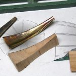
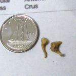
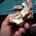
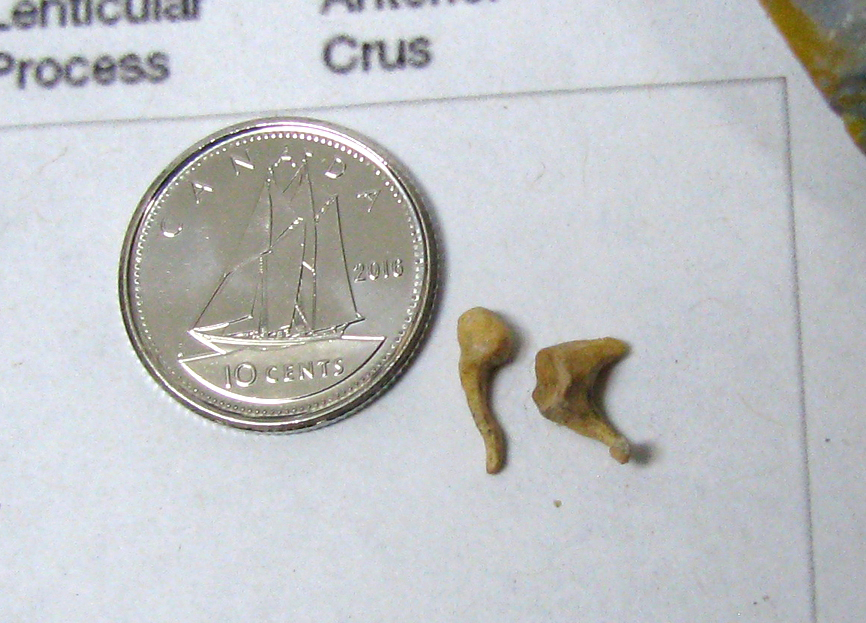
The only parts of the ear that could not be 3D-printed were the sensitive middle ear components: namely, the tympanic membrane and ossicle bones. To create these, our designer consulted a variety of anatomical drawings and scientific descriptions to better understand the shape, construction and operation of the human hearing apparatus. He then painstakingly sculpted the ossicle bones out of boxwood – selected for its stability and ease of modification – and attached them to a thin silicon membrane to replicate the shape and flexibility of a biological tympanic membrane (see Figures 11 and 12).[21] According to him, this was far and away the most difficult aspect of the project. Not only were the components exceedingly small, but affixing them in such a way as to maintain a free but structured movement between the ossicle bones and tympanic membrane – while also ensuring a certain tension in the membrane, conducive to the transmission of vibrations to the stylus – proved exceptionally difficult. This effort was necessary, however, because unless these components were assembled with a high level of anatomical accuracy, we had little hope that the instrument would function like the original once it was completed.
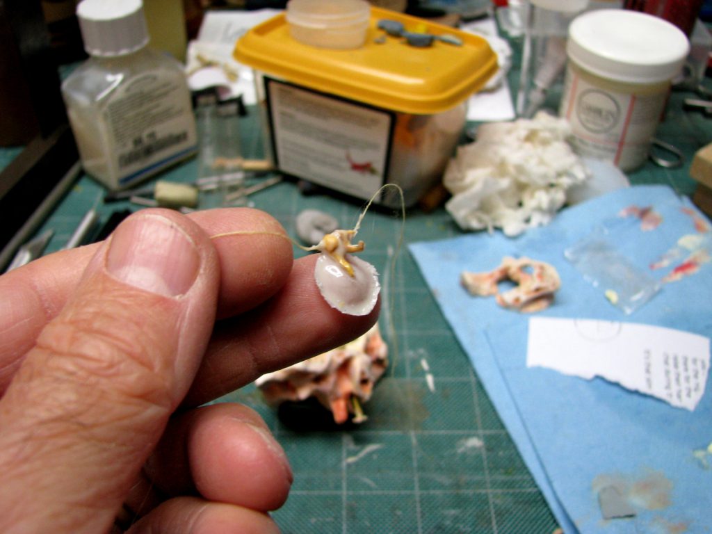
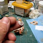
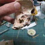
To create the sound-etching stylus – the physical constitution of which Blake (1875, p 123) described as ‘a matter of considerable importance’ – our designer endeavoured to follow Blake’s instructions to the letter. In the second of Blake’s two reports on the ear phonautograph (1876, p 112), he describes in detail the significance of attaining a stylus that was ‘very light and firm, and sufficiently elastic to bend easily when its point is pressed upon the glass plate, and should be so stiff as to have but little vibration of its own’. He also describes in detail some of the different materials he experimented with for this piece of the instrument – including ‘styles of horse-hair, bristles, cane fibres, split bamboo and the like’ – before determining that ‘the best style for the purpose was obtained by splitting long wheat straw, scraping the inner cortical substance away, and separating single fibres’ (ibid).[22] To best approximate this stylus, our designer successfully obtained several samples of split wheat straw from a farm in western Canada which he deemed to be reasonably close to Blake’s ideal. He then proceeded to attach the finished stylus to the ossicle bones inside the middle ear with a drop of hot wax (see Figures 13–15).[23]
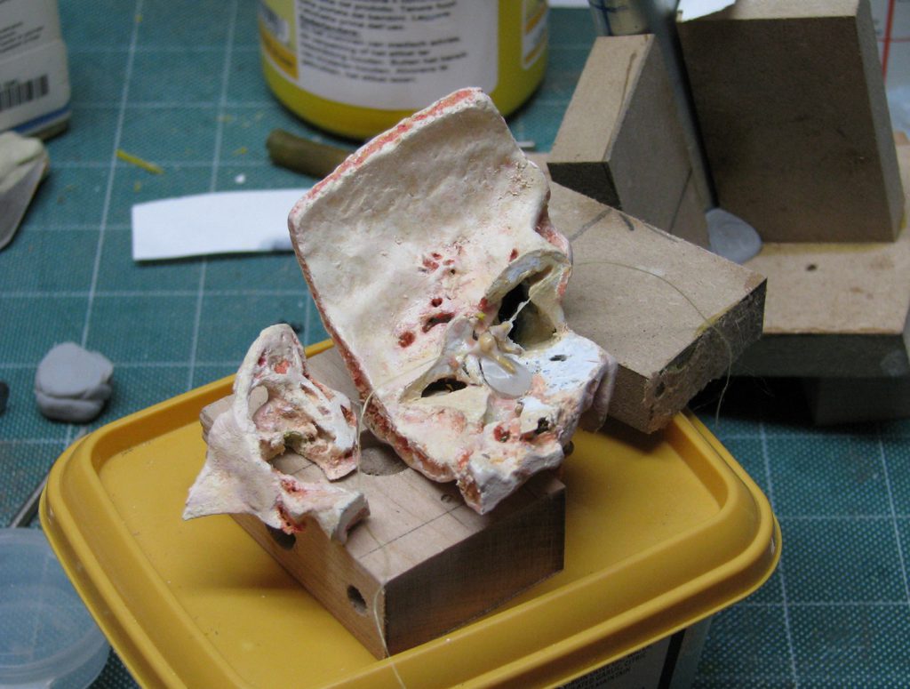
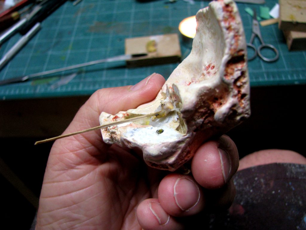
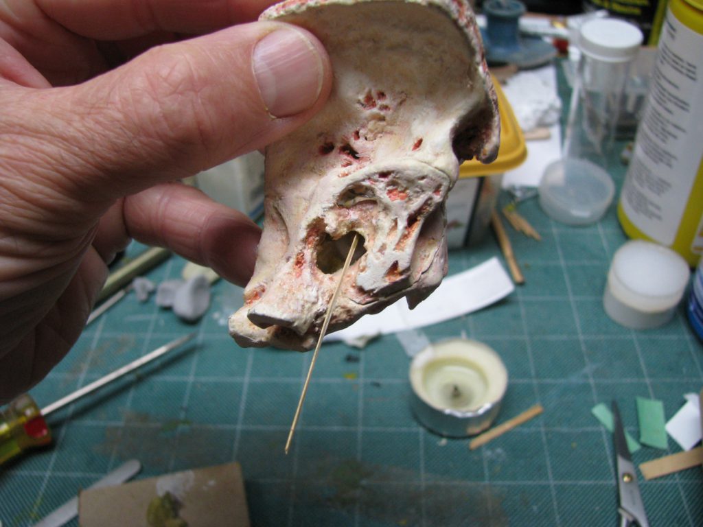
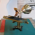
The final step in the initial fabrication phase was preparing the ear specimen for installation onto the main structure. Our designer achieved this in the same manner described by Blake in his 1876 report (pp 111–2): ‘by means of thumb-screws passing through holes bored in the squamous portion of the [skull] bone.’ Once the installation was finished, our initial ear phonautograph prototype was complete (see Figure 16).
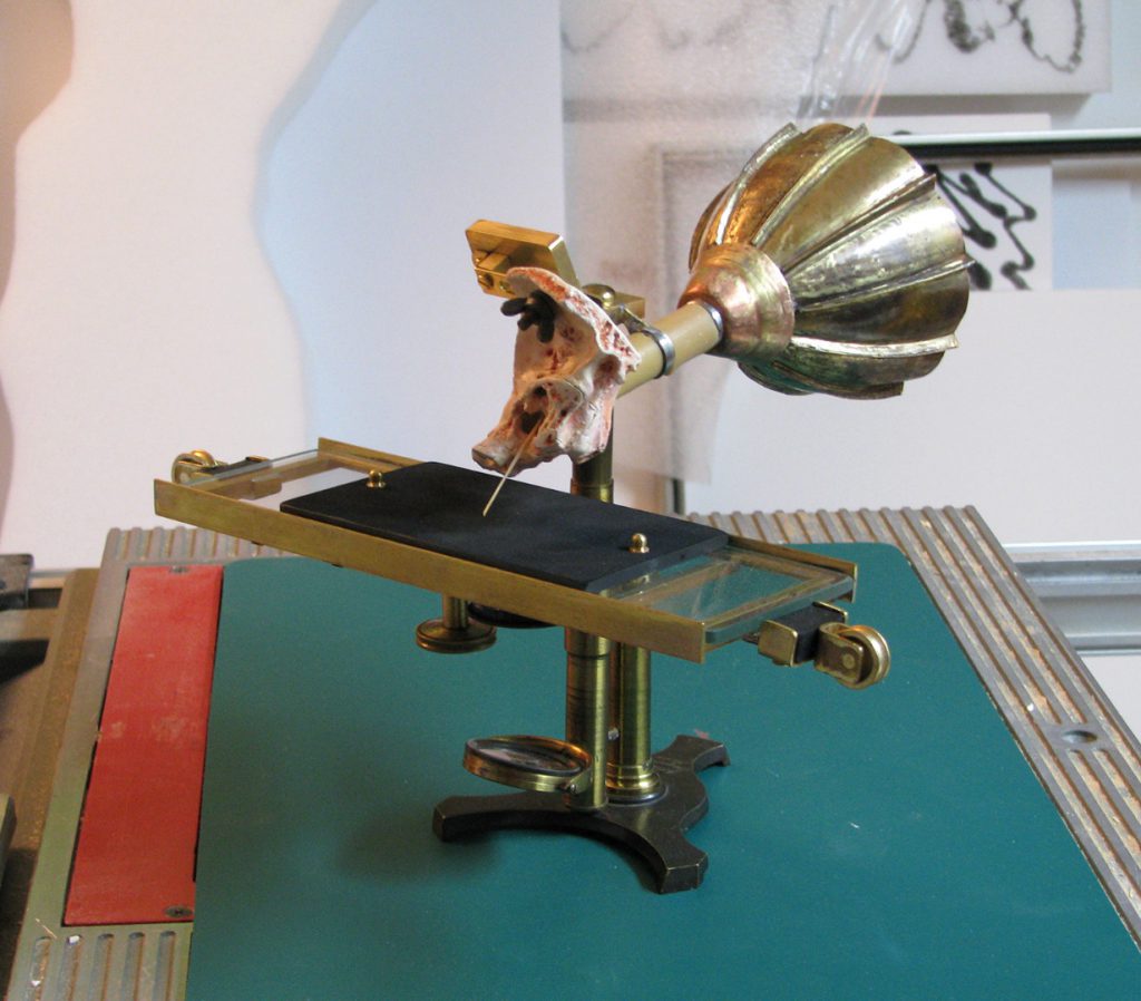
V. Revising the initial prototype
Upon completing the prototype, several issues became apparent that we had not anticipated at the outset of the build. The first problem was the overall instability of the finished structure. More specifically, the three-pronged base of the microscope appeared too small to support the weight of the moving glass assembly and the instrument became tippy and unsafe to operate. After reviewing the instrument against our reference images, it became clear that the original base was indeed larger than ours. More than this, a closer examination seemed to indicate that the base was positioned differently than most period microscopes we had reviewed in the Museum’s collection.[[24] This suggested that the base of the original instrument might have also been adapted by Blake as he encountered similar difficulties. Rather than search for a larger base, we instead endeavoured to machine one that better matched the shape and size as depicted in Bell and Blake’s reports. We enlisted a member of our production staff, Paulus Heebink, who set to work developing a base pattern that could then be cast in brass by a local machinist. Once the new base was produced, he then affixed it to the structure and inserted an additional stem extension in order to increase the overall height and stability of the instrument. While it’s impossible to say to what extent Blake would have altered the microscope structure to end up with his final version, we can say with some certainty – upon comparing our reproduction against the original images – that he either started with a larger microscope or made similar adjustments as we had.[25] Once we were done, the new prototype looked a lot closer to the original and functioned in a much more stable and usable way (see Figure 17).
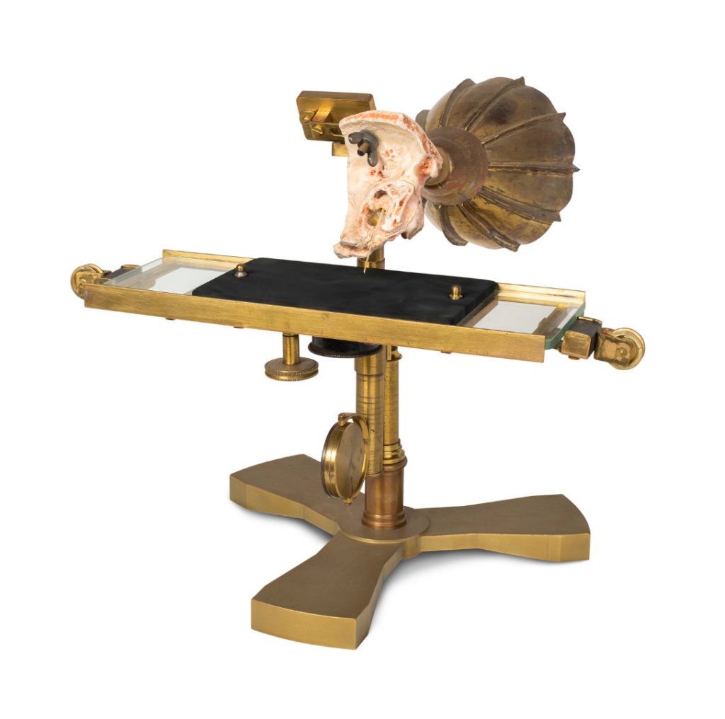
The second element that appeared problematic upon our review of the finished prototype was, surprisingly, our custom-built mouthpiece. While we were initially confident that the mouthpiece would have been made of metal, upon second glance our mouthpiece did not quite match the look of the original. Indeed, in comparing the two side-by-side, it appeared the original was much more likely made of leather or some other pliable material. This material might have been chosen in order to prevent excessive resonance from building up and passing from the mouthpiece to the ear (thereby impacting the clarity of the final etching); or it may have been selected to better mimic the fleshy constitution of a biological outer ear. Sadly, neither Bell nor Blake offer any commentary that might illuminate the rationale behind this decision. Nevertheless, we have since decided to fabricate a new mouthpiece that might bring it closer to the original so as to support further and potentially more accurate experimentation. We’re hoping to have this new and improved mouthpiece constructed and affixed to the prototype by end of next year (2020).
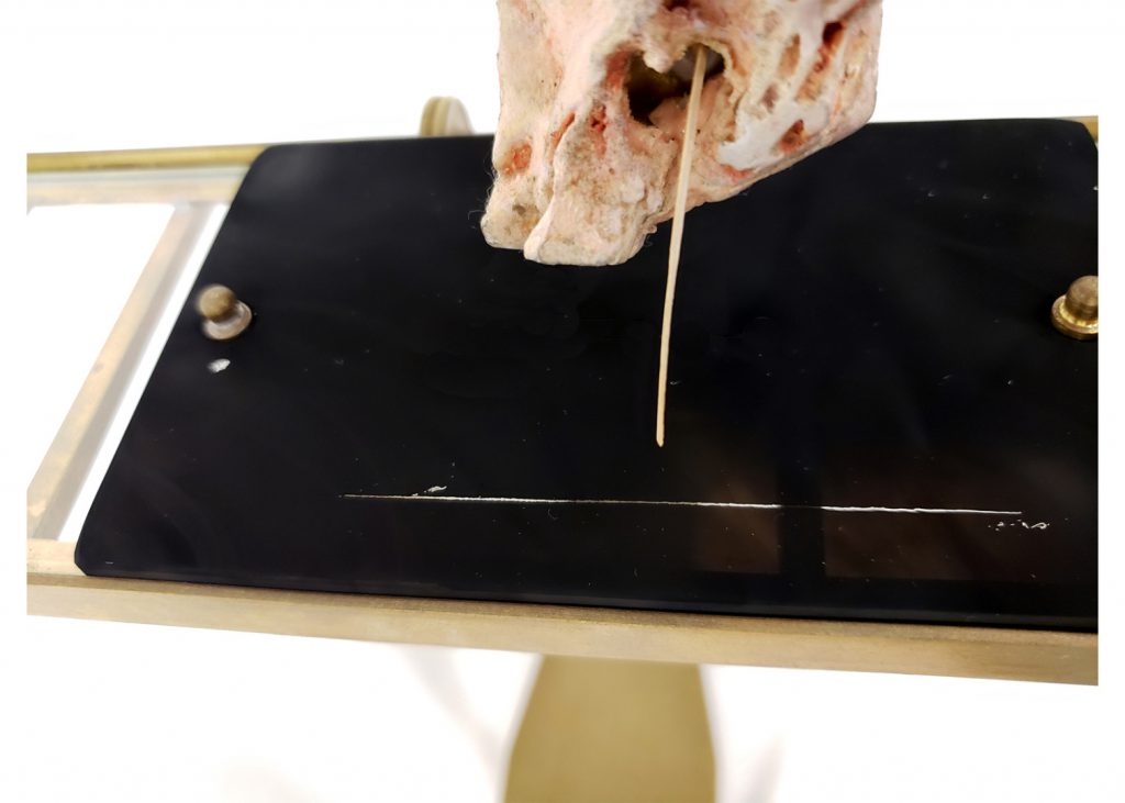
Finally, while the most exciting part of the project has been observing that – from a mechanical standpoint – the instrument operates remarkably well, the most disappointing part has been discovering that our artificial middle ear has proven to be an inadequate substitute for the real thing. While a silicon tympanic membrane was selected specifically for its thinness and pliability, preliminary experimentation suggests that it is still too stiff in comparison to that of a real human ear, and we have thus far been unable to replicate the sensitive etchings of the original ear phonautograph (see Figure 18). The question persists as to whether – one hundred and fifty years after the original experiment – there indeed exists an artificial material that could allow us to do away with this key component of the instrument. For now, it appears that the same challenge that led Bell and Blake to resort to a real human middle ear remains for us.
Research findings
https://dx.doi.org/10.15180/191206/003One of the main reasons for undertaking our ear phonautograph reconstruction effort, beyond producing a three-dimensional object to use in the Sound by Design gallery, was to test two theories regarding the potential benefit of such a project for producing knowledge that would have been difficult to access, or adequately support, through document-based research alone. The first was that we would learn something new about the object by going through the process of actually building it; the second was that we would learn something more by actually operating it. Having now been involved in both the build and operation of our reconstruction, I can say that both theories have been well-supported.
A key finding established during the fabrication phase was that the ear phonautograph was not entirely custom-made, but was instead built on the structure of an existing instrument: the nineteenth-century microscope. This finding was important, first and foremost, because it allowed us to settle conflicting reports in the secondary literature about what the structure of the instrument was actually made of. According to Charles Snyder (1974), the ear phonautograph had been built on a microscope stand, making the most likely material used in its construction brass. Yet Jonathan Sterne (2001) instead describes the ear phonautograph as having been constructed on a ‘wooden chassis’ (p 260). Crucially, neither Snyder nor Sterne offers evidential support for these conclusions, and my efforts to substantiate either claim using primary source documents have thus far proved futile. By going through the process of actually reconstructing the instrument, we were able to generate plausible material evidence to provide clarification on this discrepancy, and confirm that Snyder was most likely correct in his assertion that the ear phonautograph was built on a brass microscope base.
Operational evidence lent further support for this conclusion – specifically in relation to the circular mirror, which to this point has gone unremarked upon in historical accounts of the instrument. Upon completing our reconstruction, we hypothesised that the most probable use for the mirror would have been to reflect a focused light up through the bottom of the smoked glass plate, which would make the etching more acutely visible to the speaker while the instrument was in use. However, as we began experimenting with the instrument, this possibility seemed increasingly unlikely. Given the comparatively short length of the smoked glass plate, and the speed at which it needed to pass beneath the stylus in order to obtain a usable etching, we determined that the smoked glass plate could only be in motion for two to three seconds before it needed to be reset. Judging by the concentration it took to speak clearly into the mouthpiece, the difficulty we had seeing past the mouthpiece while speaking into it, and the limited window of time (two to three seconds) available to make any meaningful adjustments to the instrument while in use, we could establish no benefit of using the mirror to assist with monitoring an etching while in progress. It seemed far more likely that any observations or adjustments were carried out only after the smoked glass plate had finished passing under the stylus, and the etching was completed. Indeed, we found it much easier to examine an etching by removing the smoked glass plate from the bed rather than attempting to examine it in situ, and Blake himself remarked: ‘With so delicate a mechanism, and upon so small a scale, many of the tracings are of necessity microscopic, and as such are best exhibited by means of [a] magic lantern’ (Blake, 1875, p 124).[26]
A second outcome of these preliminary observations was that they unsettled our own previous understanding of the ear phonautograph as a highly-refined scientific instrument, engineered to the exacting standards of late nineteenth-century laboratory research. Having read Bell and Blake’s carefully-worded research reports, and having studied the only two surviving images of the ear phonautograph – both thoughtfully composed and staged – this seemed at the outset to be a reasonable assumption. Yet what we found instead, by going through the process of reconstructing the instrument, was that the ear phonautograph was less refined than our preliminary textual research had led us to believe. Indeed, elements of the instrument’s main structure – including the extraneous mirror, non-standard base, and even the rudimentary thumb-screw used to attach the ear to the instrument – all seemed to present the ear phonautograph as less a final production model than a Frankenstein-type object made from ‘hacking’ existing technology to suit an altogether different set of purposes.[27] To say that the object was hacked is not, of course, to say it was a hack-job. While the ear phonautograph may not have been manufactured to the high level of refinement we had initially expected, it did suit its functional purposes quite well. If anything, the ability of Bell and Blake to actually produce the instrument given the technical and financial restrictions they were presumably under speaks volumes about their resourcefulness and creativity.[28] Perhaps the biggest takeaway from this observation, then, was how it contributed to a rather interesting and unexpected demystification of the process by which nineteenth-century scientific innovators like Bell and Blake would have worked. Rather than present an image of two pioneering inventors creating entirely new technologies from scratch, our findings instead began to paint a picture of two pragmatic opportunists that bear more than a passing reference to who we might call object hackers today (see Rosner and Bean, 2009; Kolko et al, 2012).
From an operational perspective, we also discovered that the connection to the microscope, while almost certainly a product of convenience, was not purely incidental nor was it inconsequential with respect to the overall functionality of the instrument. Having now carried out a series of preliminary tests with our reconstruction, we have determined that there were indeed mechanisms inherent to the original microscope that served an important function in its operation. We can confirm, for example, that the adjustable microscope stem permitted us to easily raise and lower the glass plate to adjust contact with the stylus above. This was an essential feature for getting the exact right amount of contact pressure between the stylus and the smoked glass plate: too much pressure, and the stylus tended to bend and stick when the glass plate underneath it began to move; too little, and it would fail to maintain consistent contact, and thus produce an incomplete etching. Another useful feature was the canting mechanism – also integral to the microscope structure – that permitted us to tilt the entire glass carriage down to the left or right, so as to achieve the best angle of contact between the stylus and smoked glass plate. This was essential for achieving a smooth drag of the stylus, for if the angle – ‘inclined slightly toward the direction in which the carriage moves’ (Blake, 1876, p 112) – was not just right the stylus tended to stick and skitter across the glass while it was in motion. These observations suggest that while a microscope may have simply been the most convenient structure for Bell and Blake to use as the base for their instrument, there were indeed elements that would have proved extremely useful – and if our experience is any indication, essential – to its successful operation.
This leads to a final reflection concerning the status of the ear phonautograph as a compelling historical point of connection between the microscope and the telephone. By demonstrating, on the one side, a clear physical and functional link between the microscope and ear phonautograph, our research helped solidify an epistemological link between the two as operating within a dominant observational paradigm. Much as the common microscope permitted scientists to render the invisible visible, so too was the ear phonautograph designed – literally on the foundation of this well-known observational technique – to do the same by rendering invisible sound waves observable as visible etchings. This supports Jonathan Crary’s (1990, p 97) claim for the dominance of vision, and proliferation of what he calls ‘techniques of the observer’, which informed many of the priorities, strategies and outcomes of nineteenth century scientific practice. On the other side, if we take Bell at his word that it was the ear phonautograph that provided him with the technical insight he required to develop the telephone, then our reconstruction allows us to bear material witness to the very catalyst of this insight: the vibrating middle ear components at the centre of the instrument. By making the ear phonautograph available to researchers and museum visitors, we can now provide the occasion for further experimentation, discussion and understanding, of the role of the ear phonautograph in the historical development of the telephone.
We might go a step further. By setting up a comparative demonstration of the ear phonautograph alongside several other late nineteenth and early twentieth-century sound technologies that followed it – including the telephone, but also the microphone, phonograph, gramophone, radio headset and electrically-amplified loudspeaker – we could use our reconstruction as a means to support Sterne’s (2001, p 260) larger claim that the human ear became, in the ear phonautograph, a legible point of consolidation in the emergence of a more general ‘tympanic principle’ that enabled the development of a number of historically significant sound technologies, the telephone being only one. These possibilities speak not only to what we were able to learn in our short time building and experimenting with the instrument, but the future research and demonstration possibilities of the instrument now that we have it in our long-term possession. Just as Bell and Blake’s original ear phonautograph uncovered new potentials unforeseen at the time of its creation, it is hoped that our reconstruction might too contribute to new research insights and opportunities that we are only now beginning to imagine.
Tags
Footnotes
Back to text
Back to text
Back to text
Back to text
Back to text
Back to text
Back to text
Back to text
Back to text
Back to text
Back to text
Back to text
Back to text
Back to text
Back to text
Back to text
Back to text
Back to text
Back to text
Back to text
Back to text
Back to text
Back to text
Back to text
Back to text
Back to text
Back to text
Back to text


